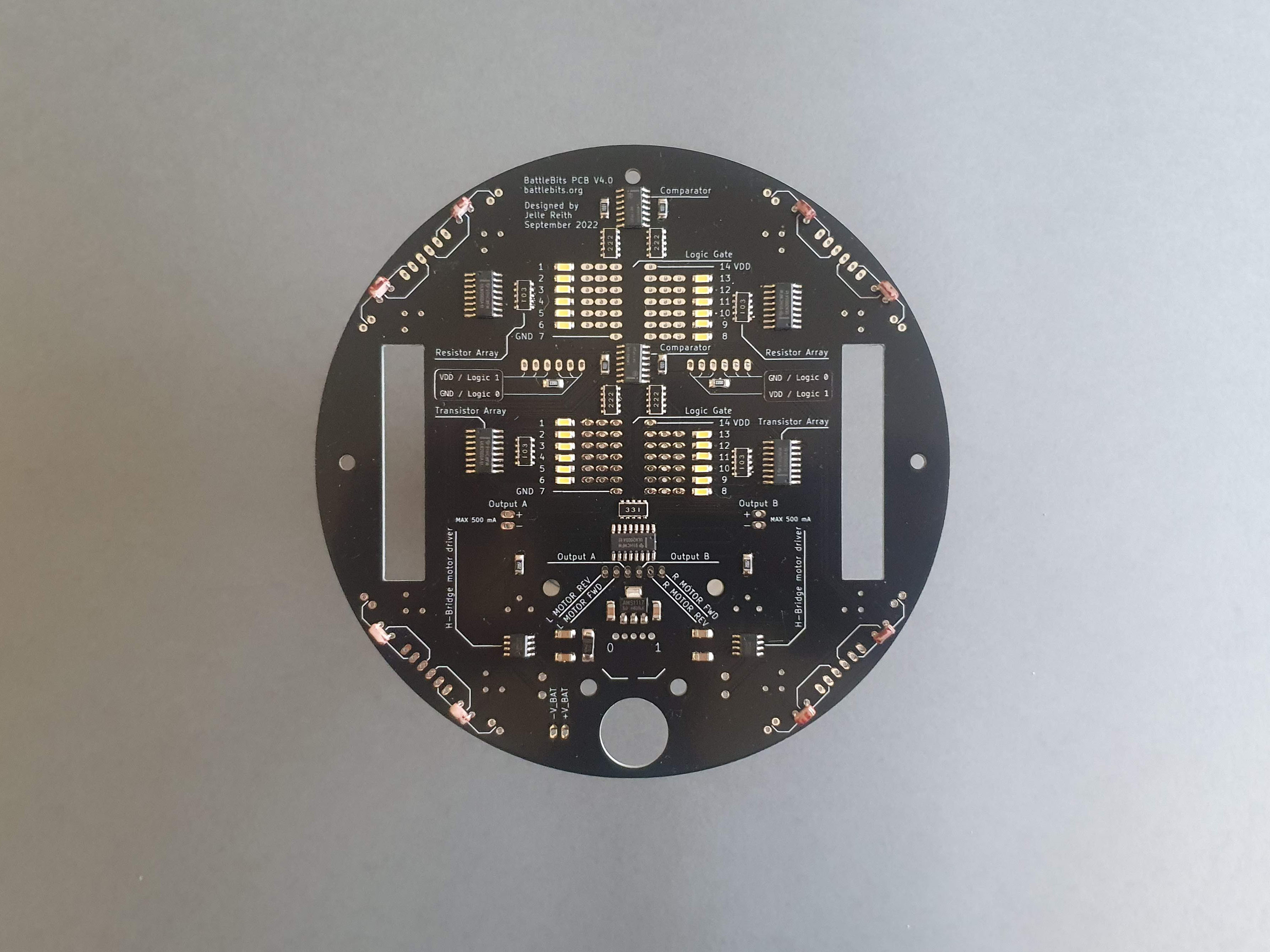
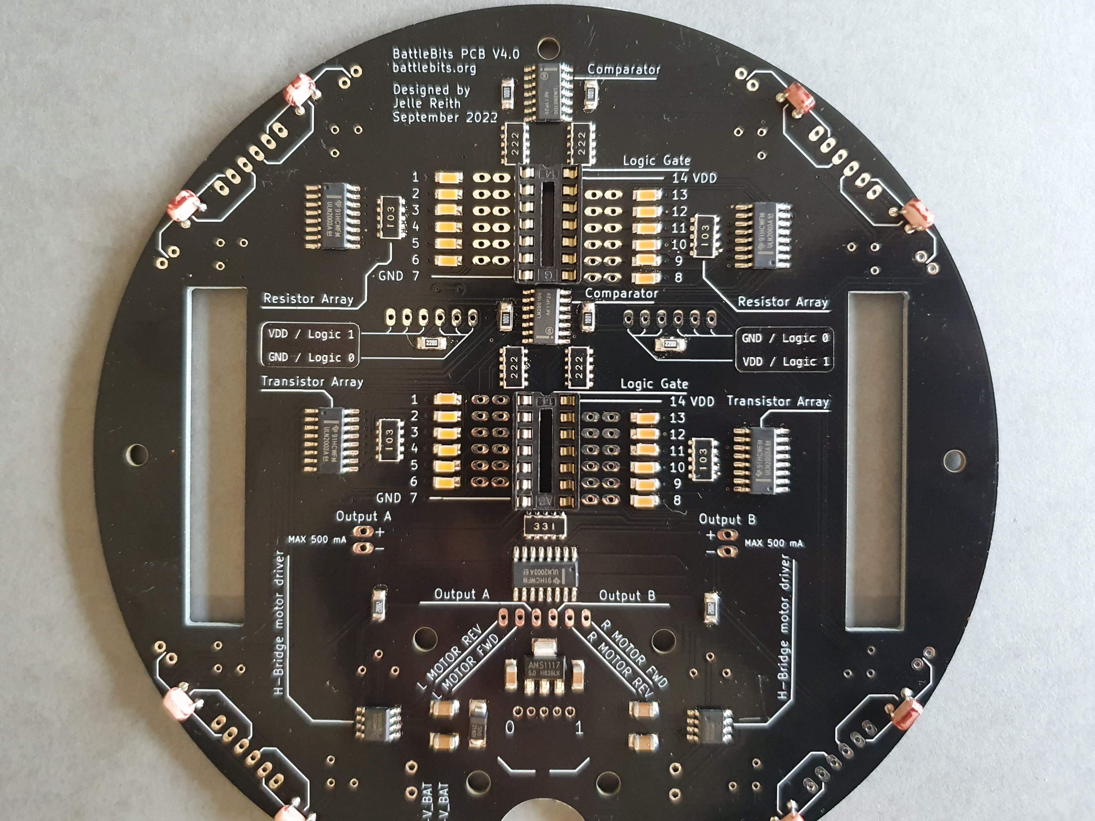
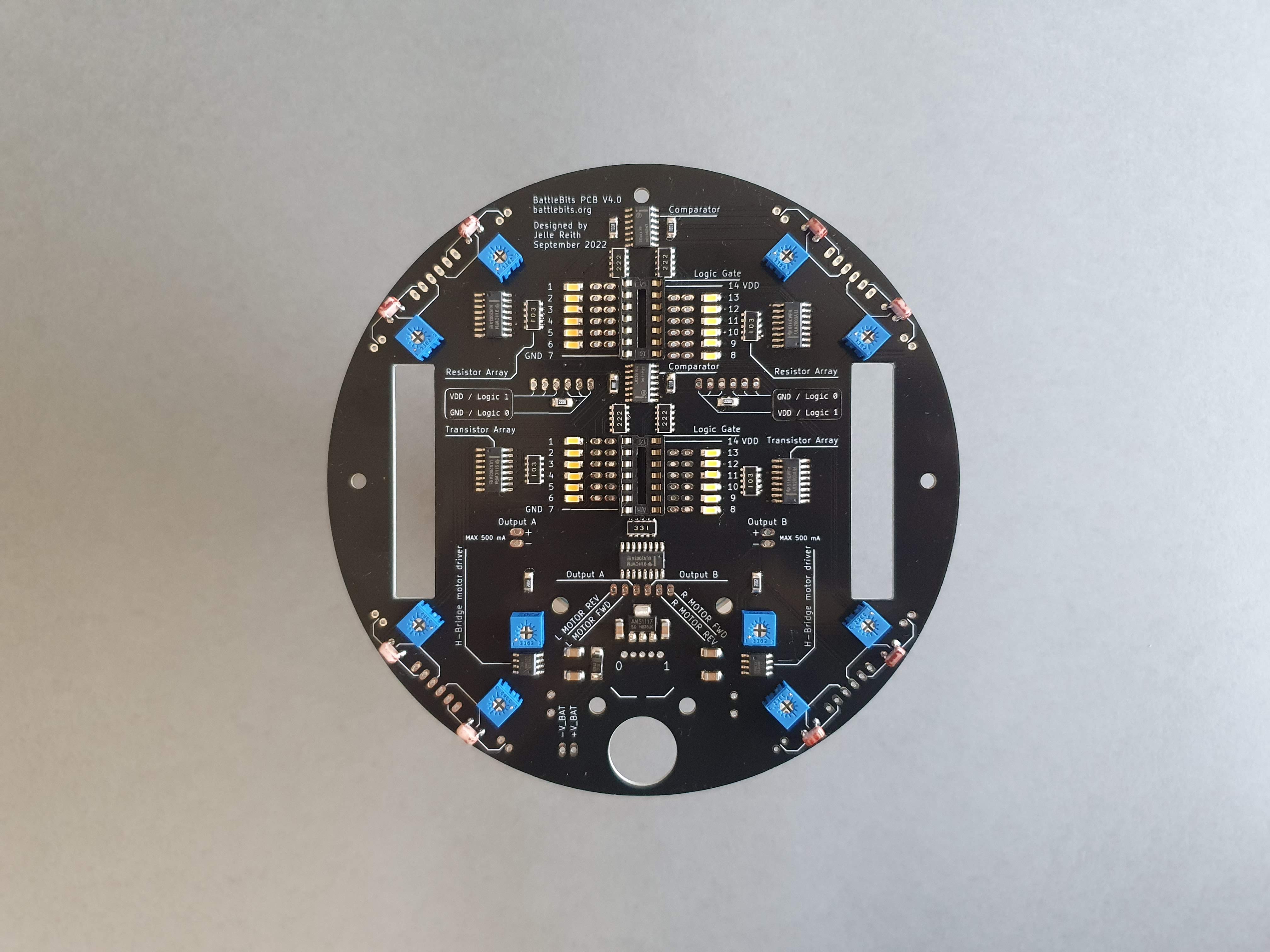
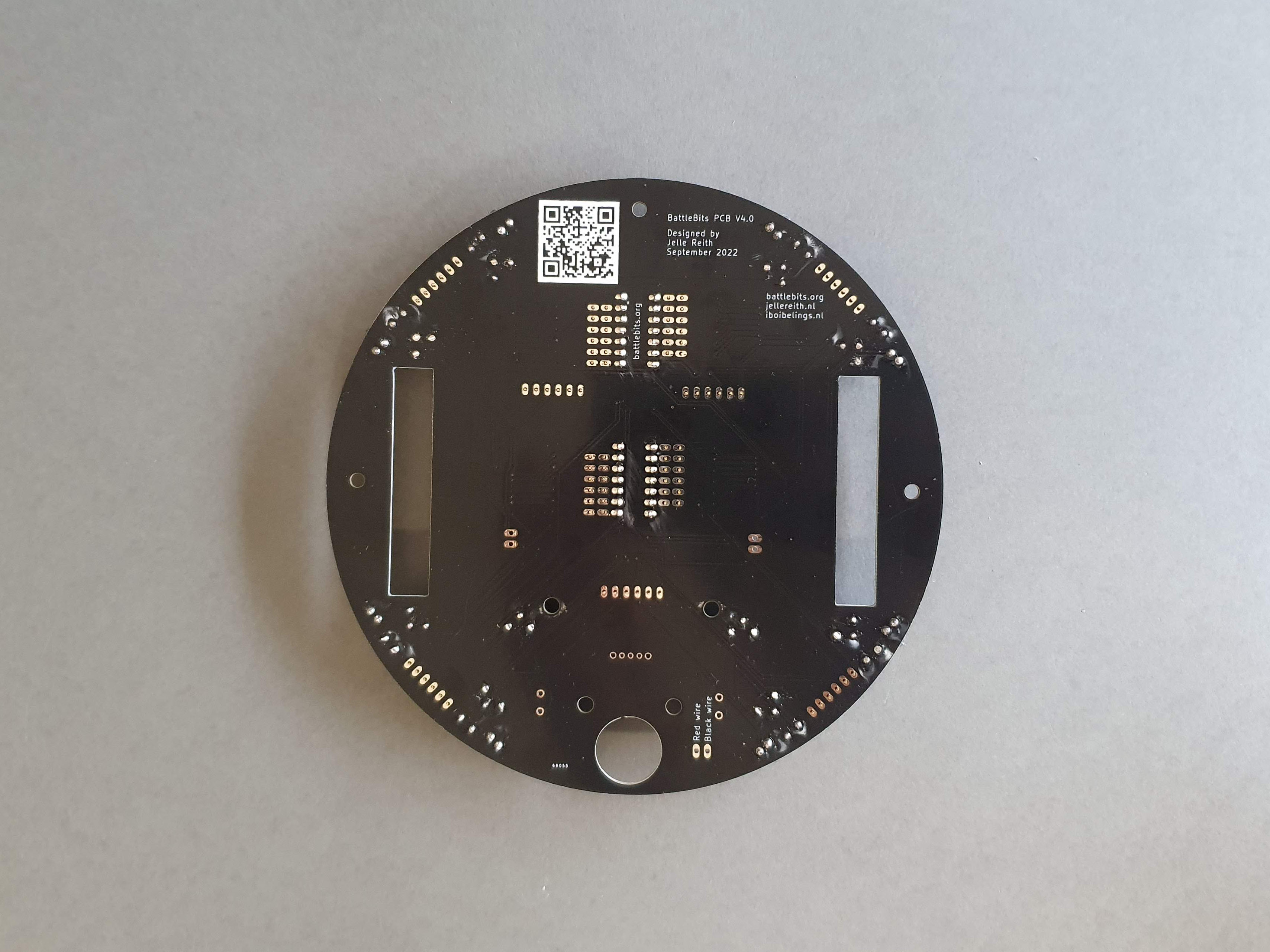
Appearance
BattleBits
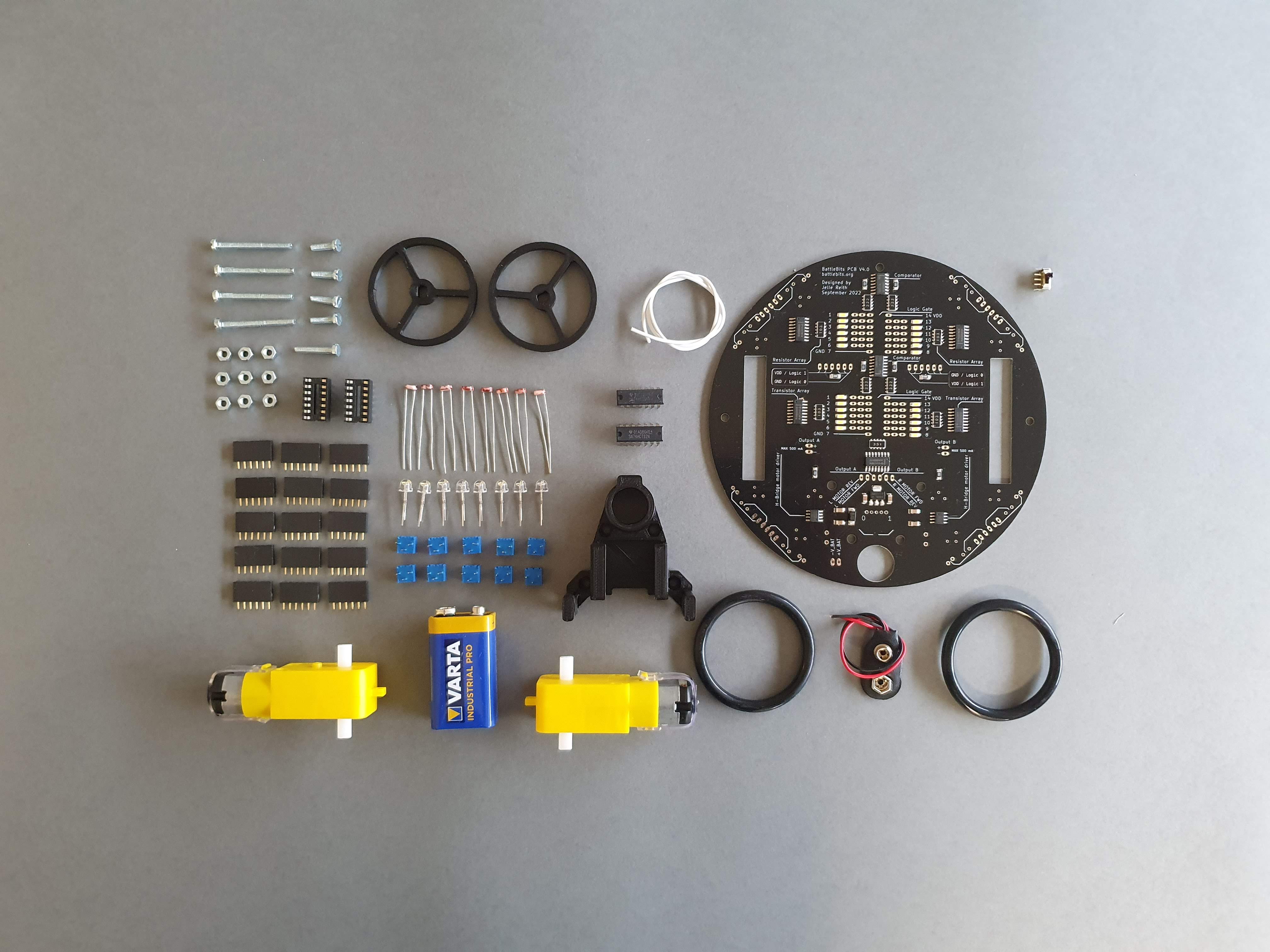
Contents of the package & tools needed
Your kit should contain the following items:
- 2 x Wheels
- 1 x Wheel base
- 1 x White wire
- 2 x 50mm o-ring
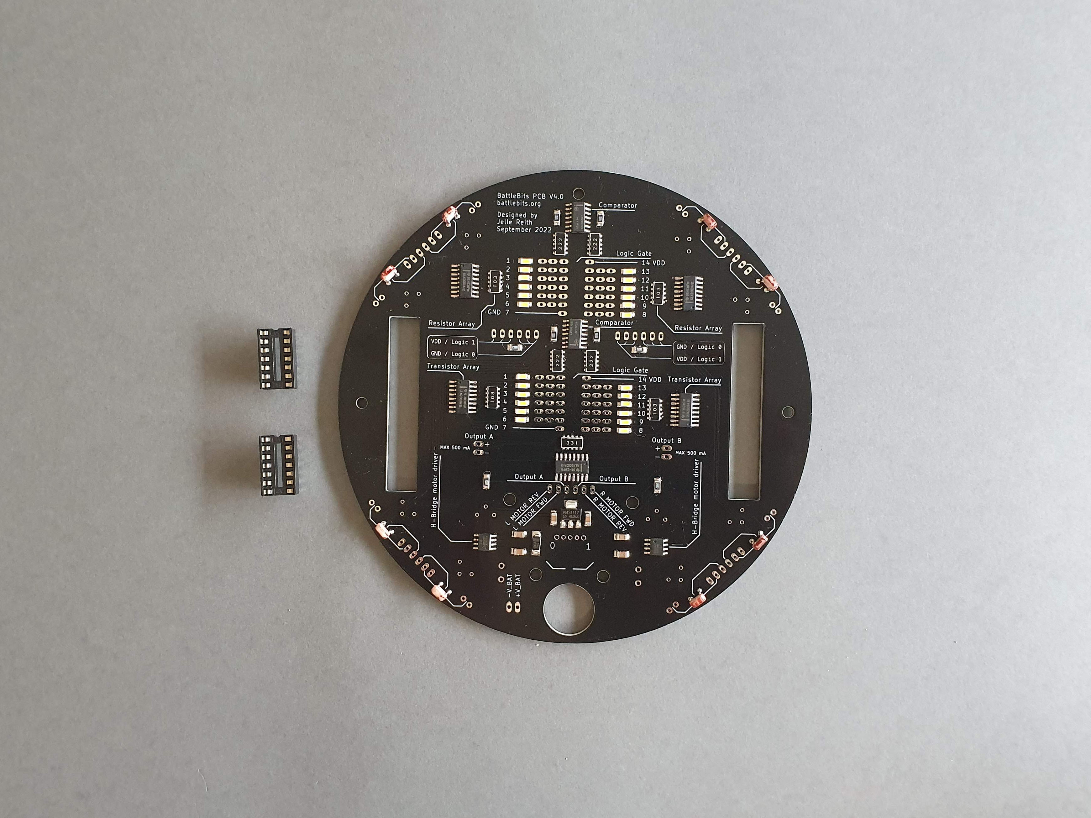
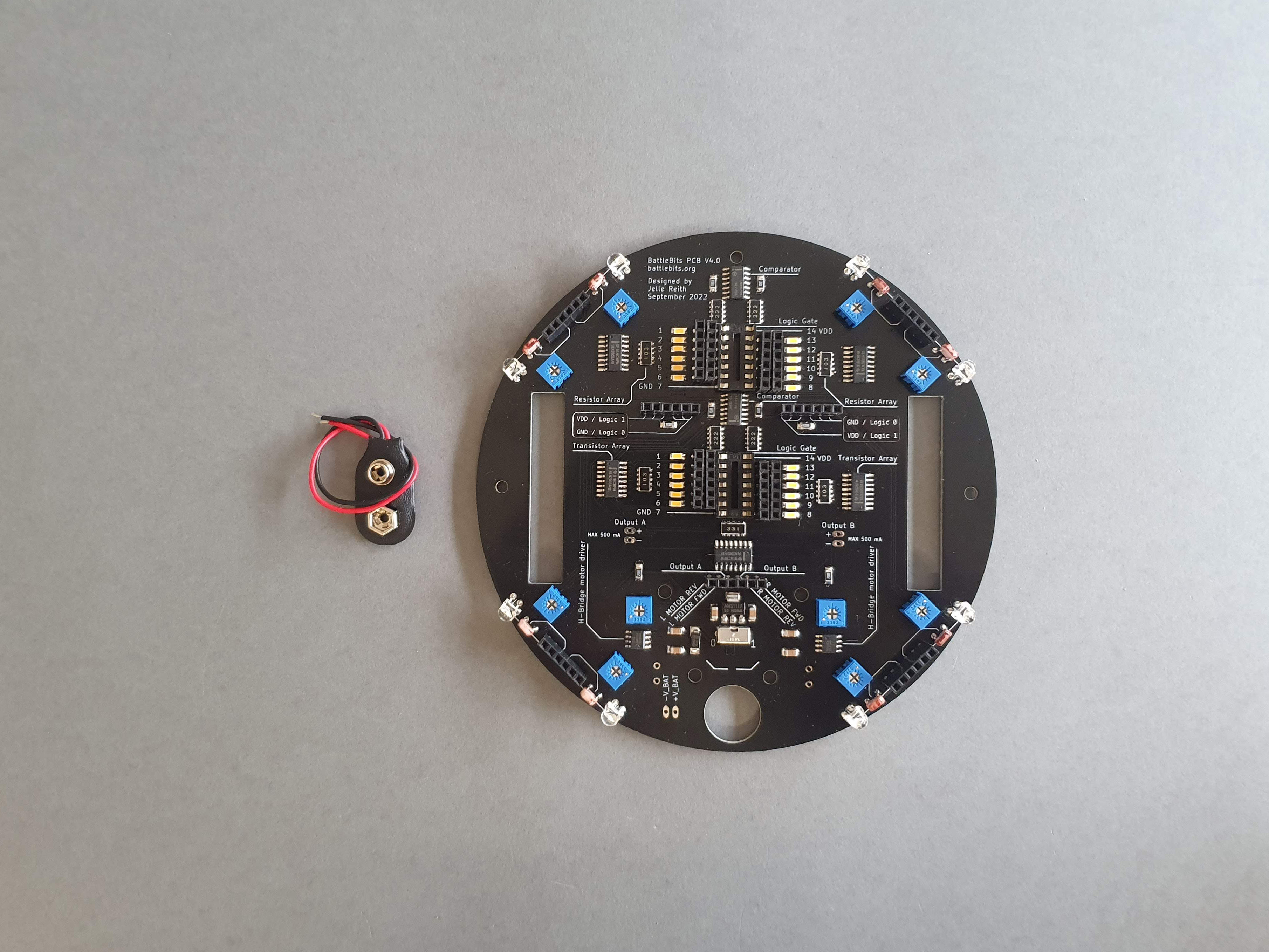
- 1 x BattleBit PCB
- 1 x 9V battery
- 2 x Logic gates
- 2 x Dip-14 socket
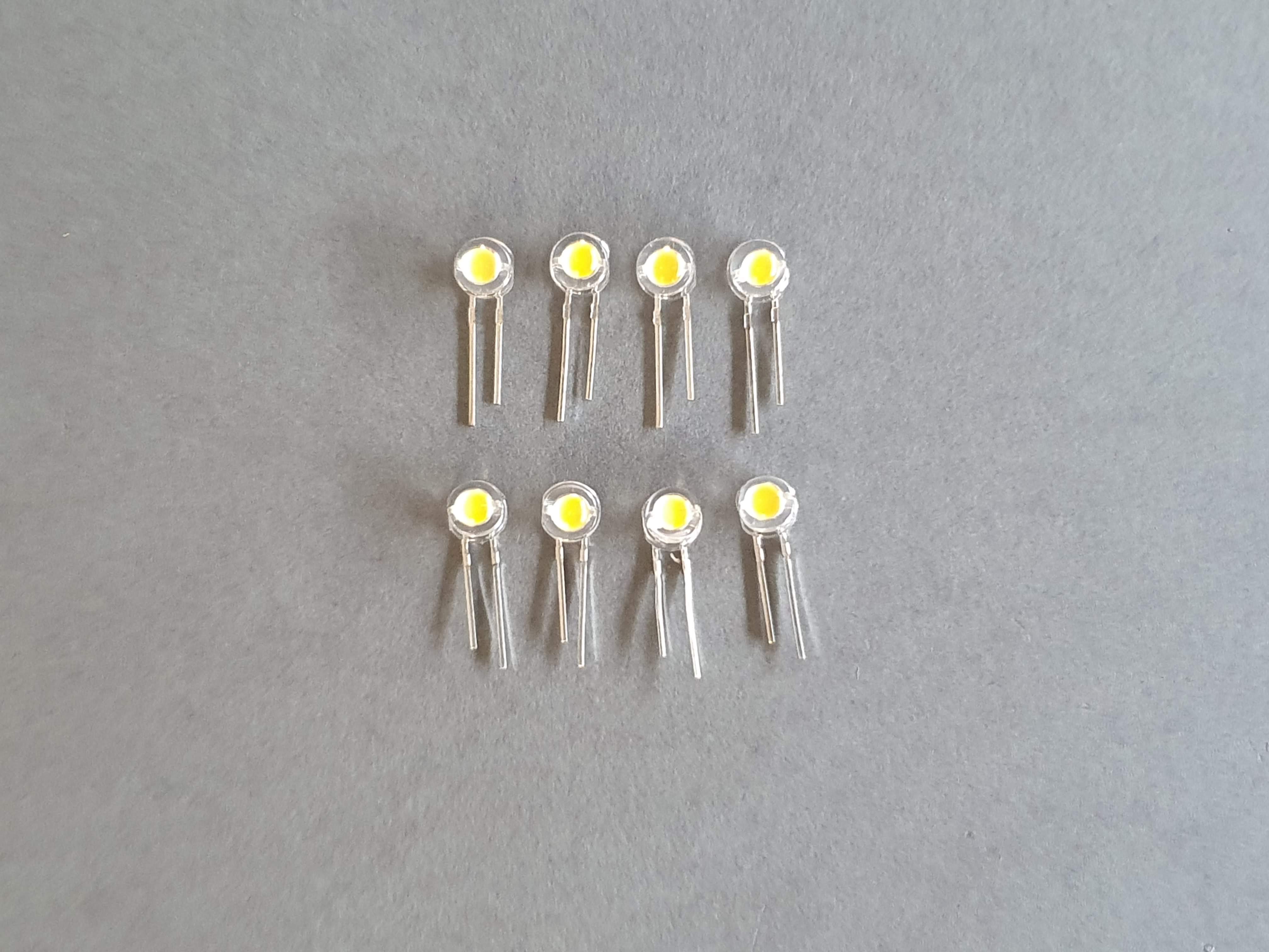
- 8 x 5mm warm white LED
- 8 x LDR ( Light Dependent Resistor)
- 4 x m3 30 mm bolts
- 4 x m3 10 mm bolts
- 1 x m3 18 mm bolt
- 9 x m3 hex nuts
- 15 x 6 pin female Headers
- 2 x Yellow Gear Motors
- 1 x On/Off switch
- 1 x 9v battery connector
- 10 x 20k potentiometer
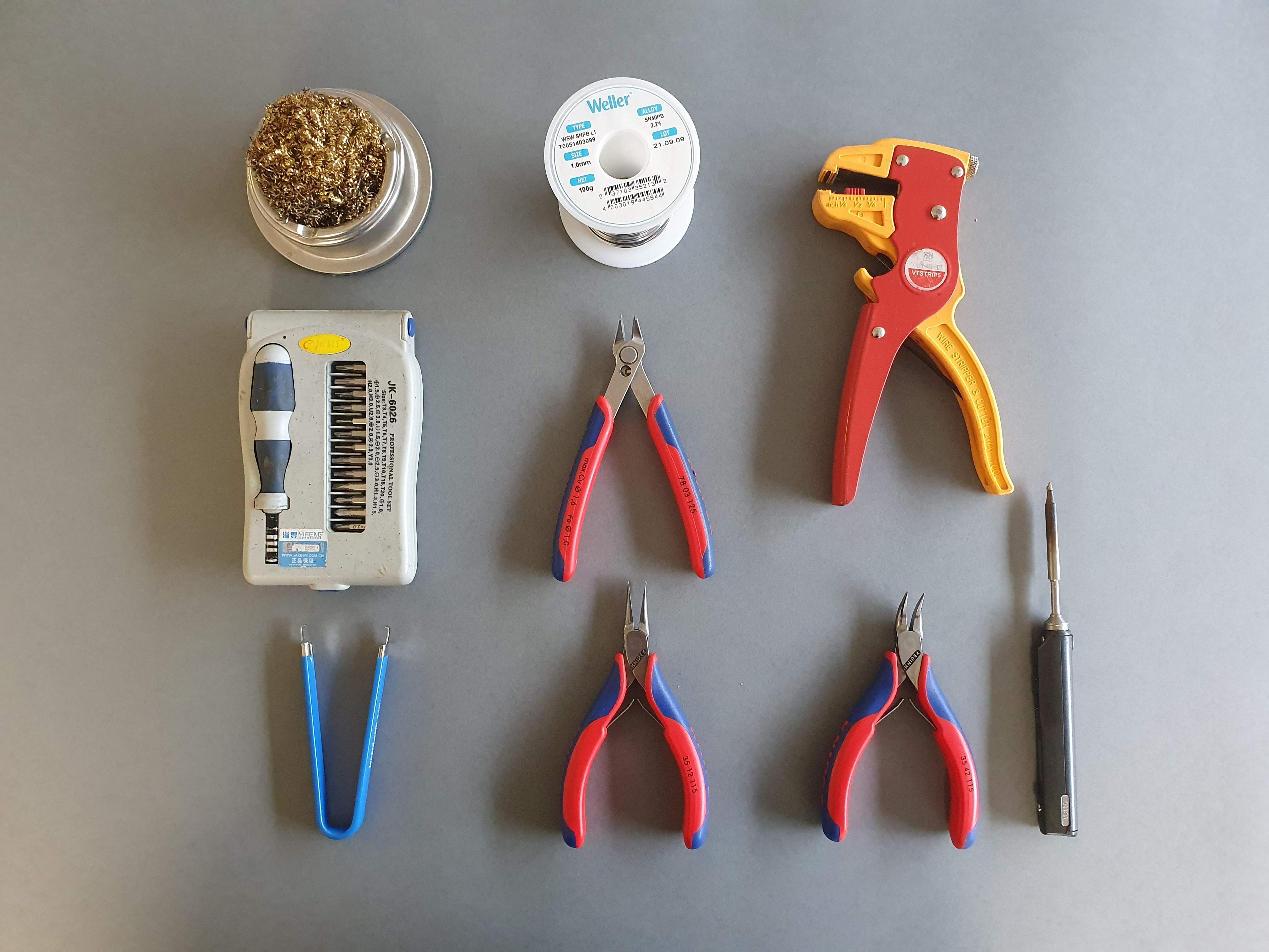
Tools Needed:
- Soldering iron and a damp sponge to clean soldering iron
- Soldering tin
- Set of small screwdrivers
- Couple of pliers
Tools you can get from Jelle and Ibo
- IC extractor
- 9V battery
- Jumper wires
- Different logic gates (see "Advanced logic gates" )
Step-by-step guide:
This is a detailed manual for assembling the BattleBit. If something is unclear, feel free to ask Ibo or Jelle!
Soldering the LDRs (Light Dependant Resistors / photoresistors)
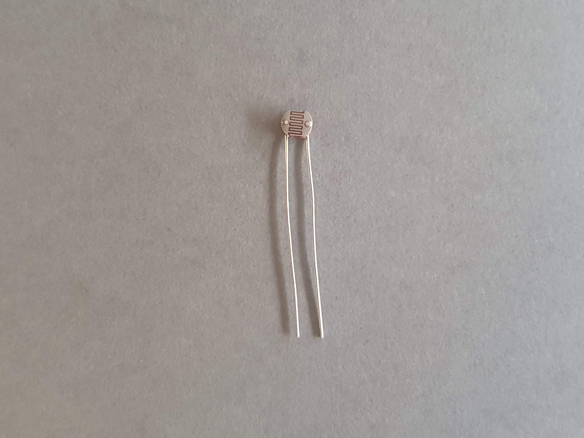
A Light Depentent Resistor is a kind of variable resistor. The resistance of this device changes with the amount of light that hits it. The LDR that is supplied in the kit is the 5528 LDR. It has a negative resistance coefficient meaning the resistance decreases when the amount of light increases
Materials:
- BattleBit PCB
- 8 x LDR
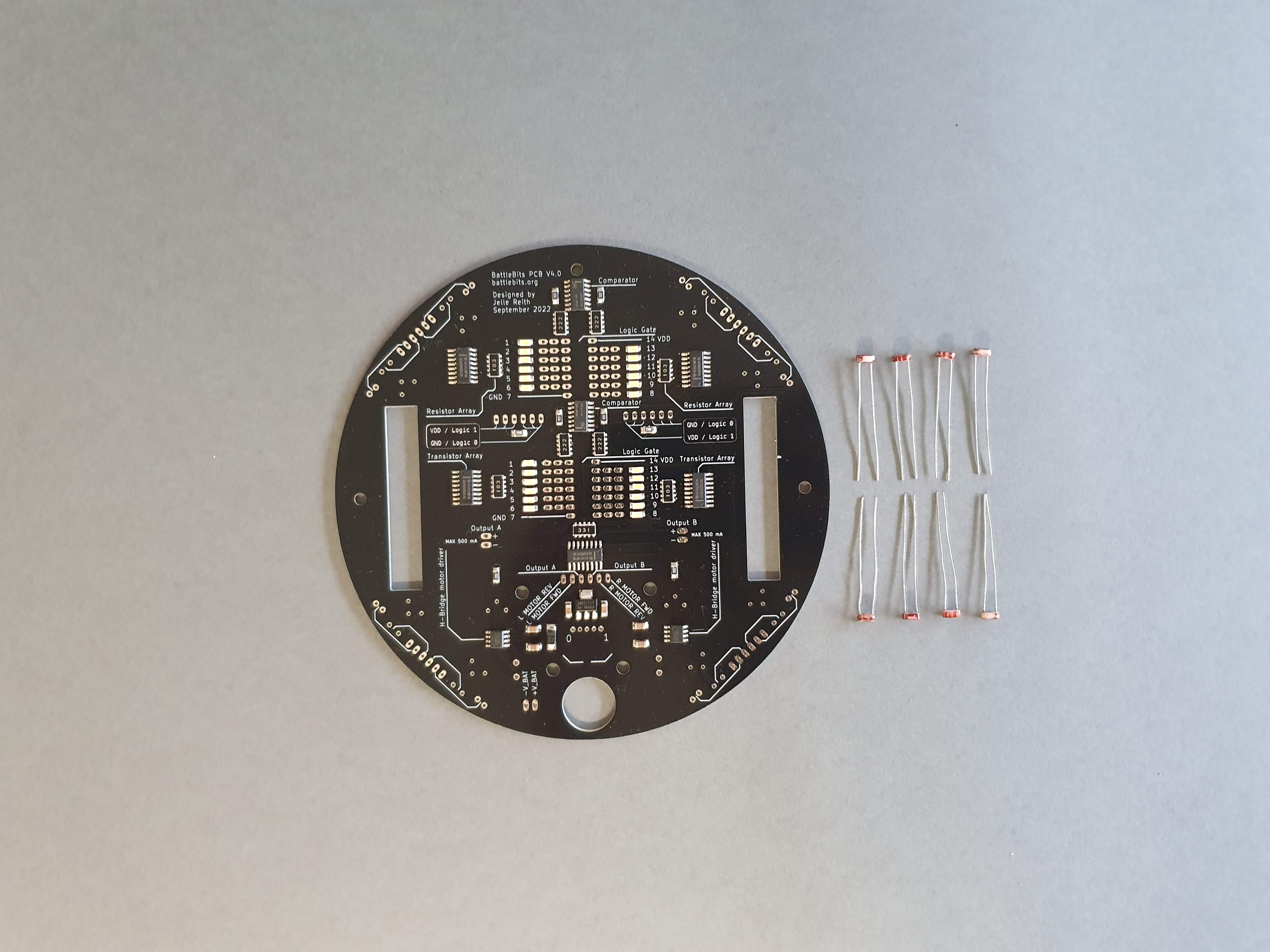
Steps:
- 1: Bend the legs of four of the LDRs. LDRs don't have a polarity so it doesn't matter which way you bend them.
- 2: Place the LDRs in de following way:
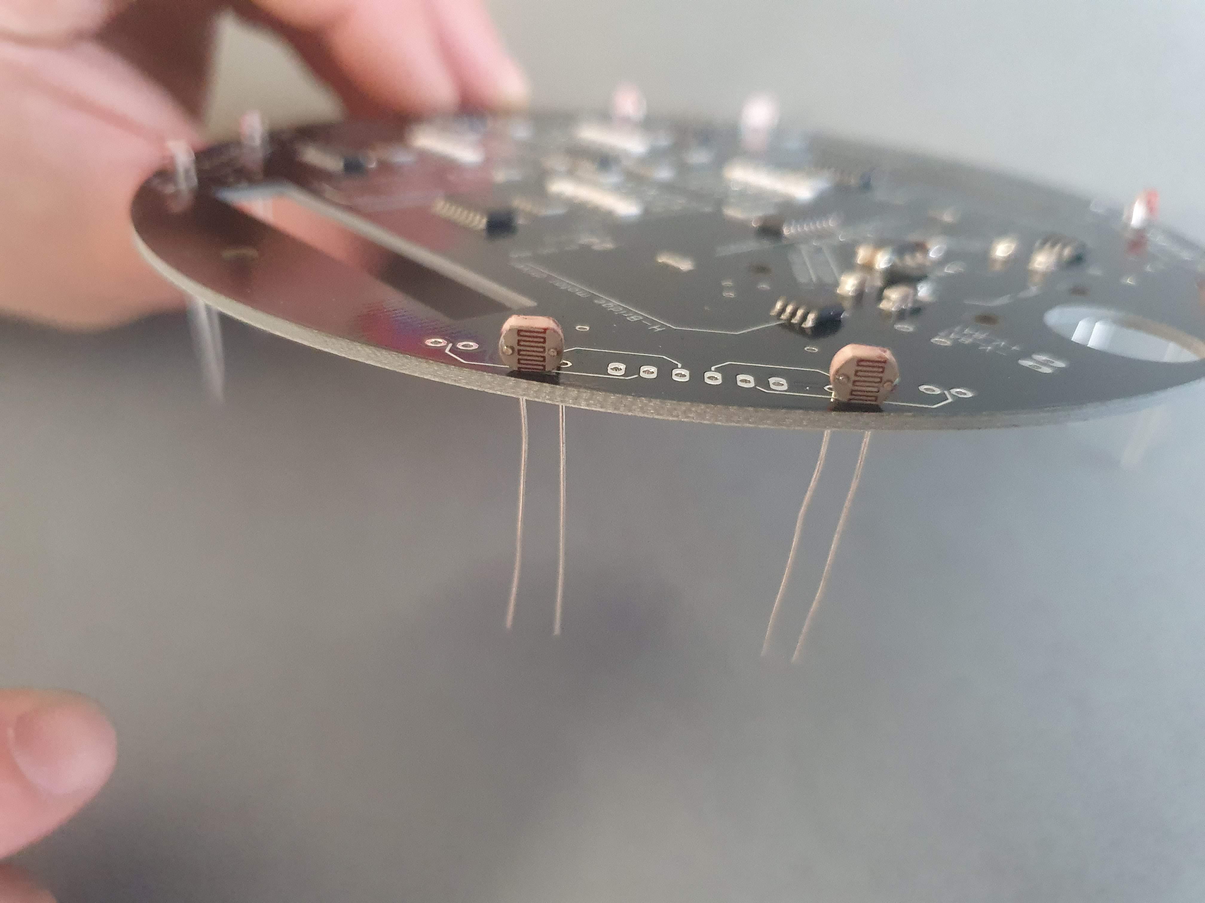
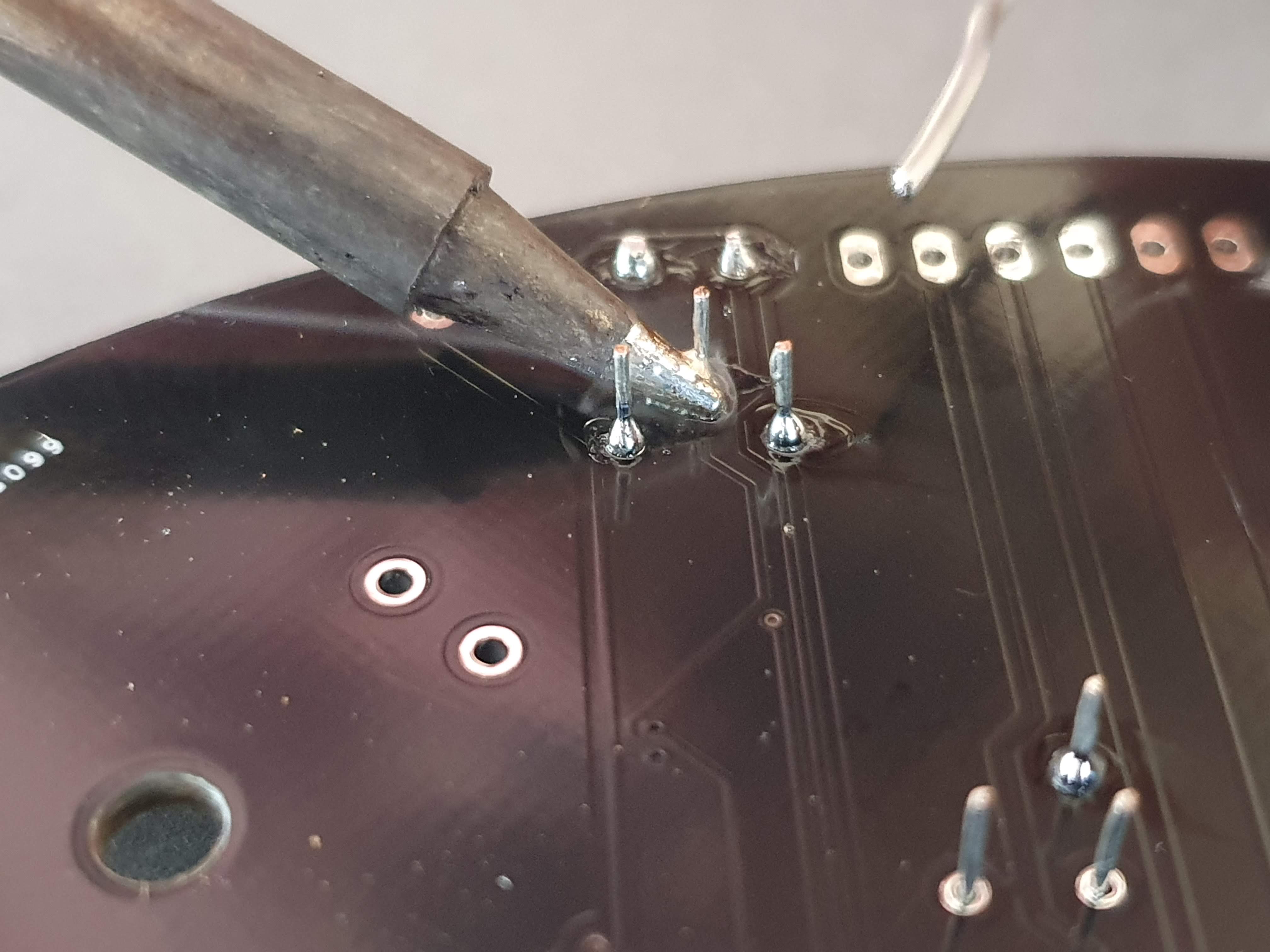
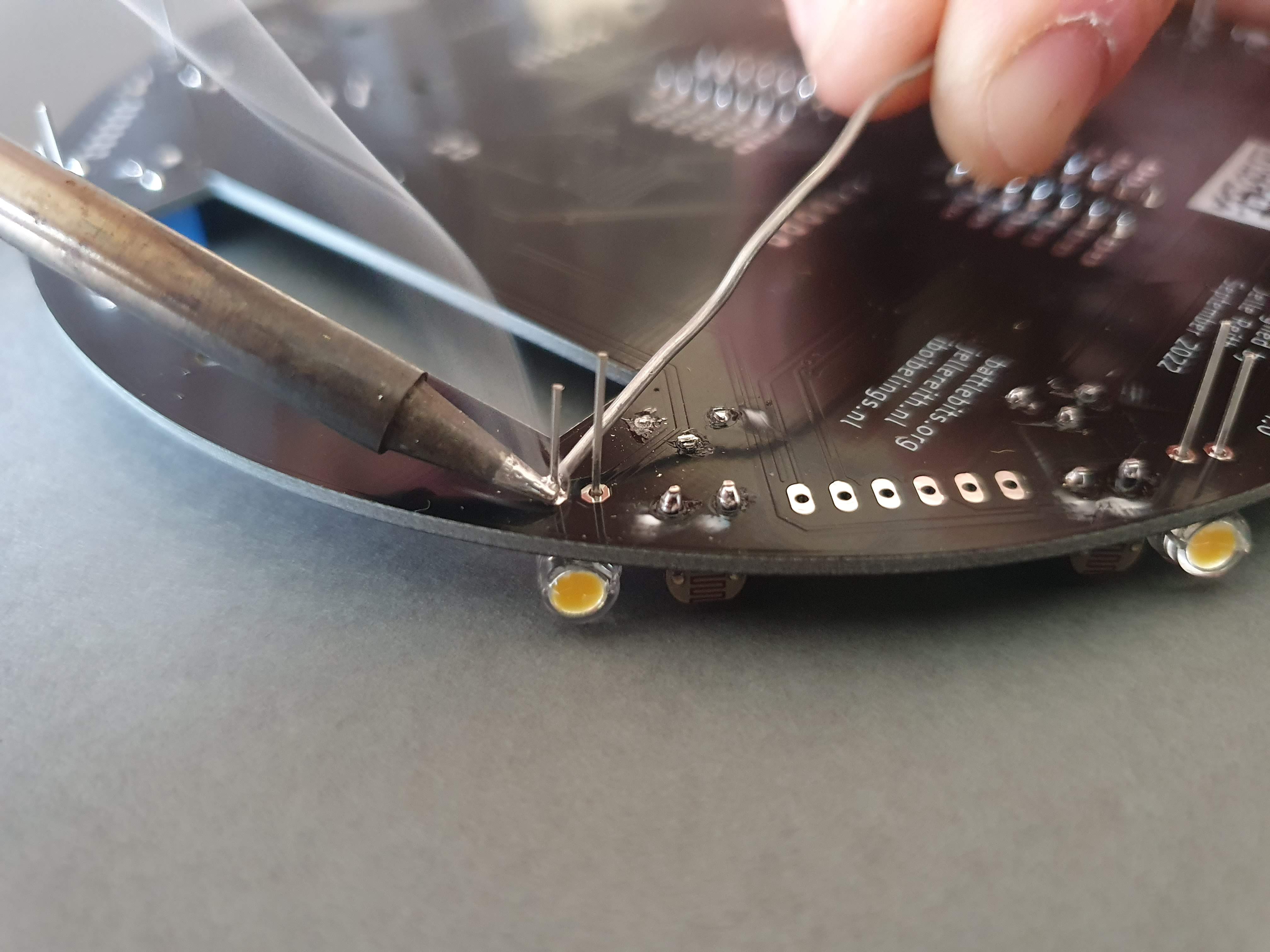
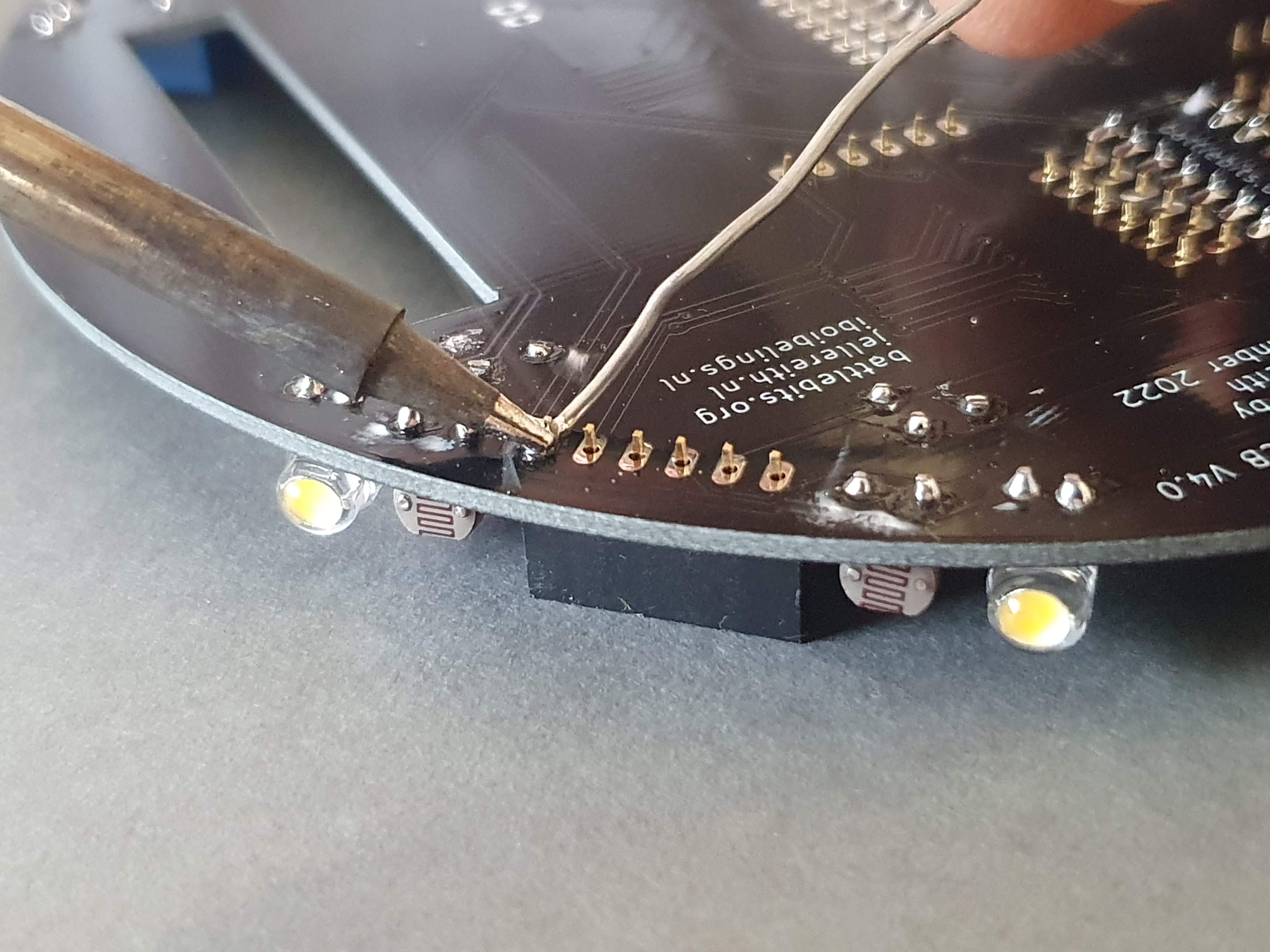
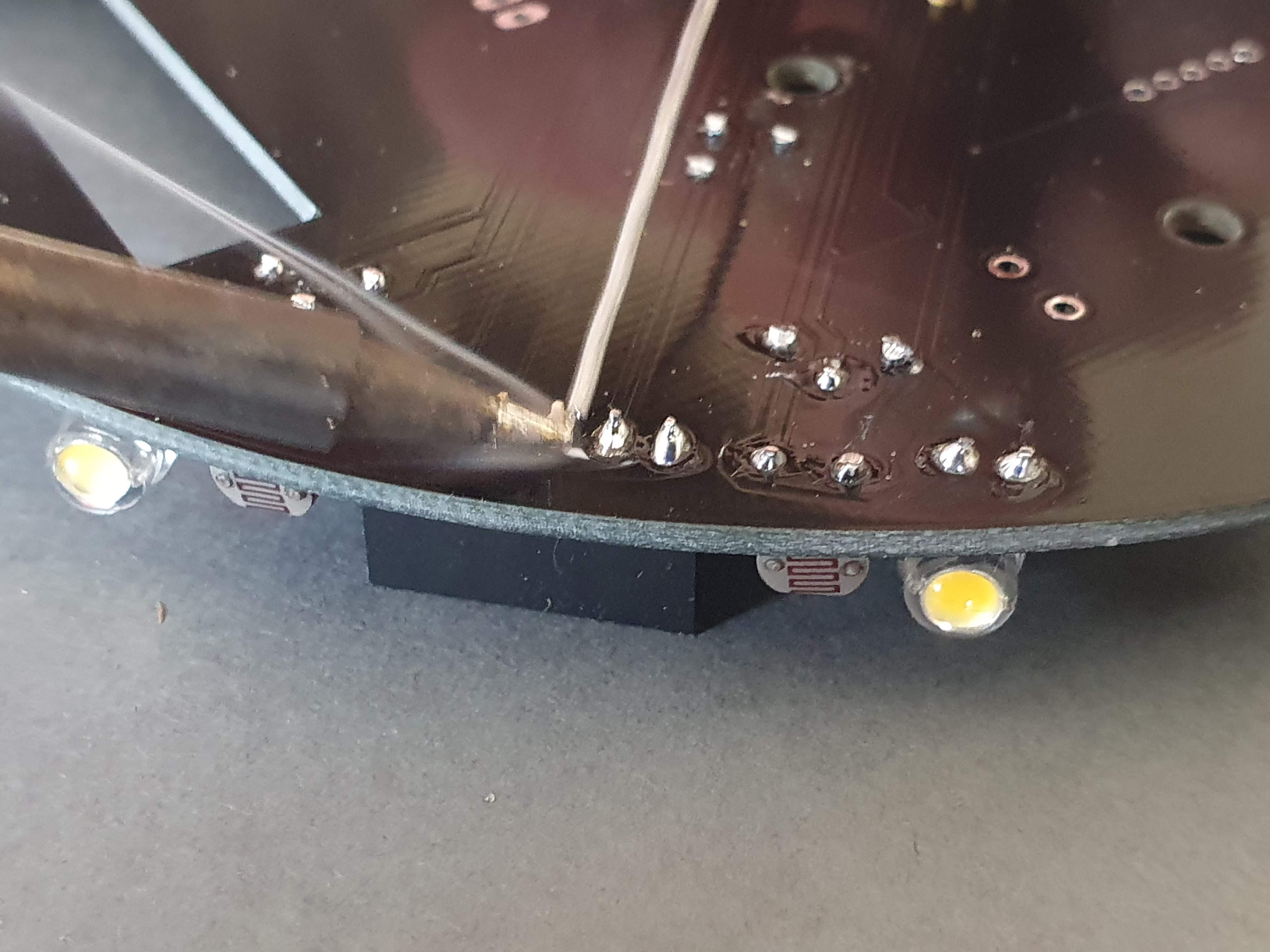
- 3: Solder one of the legs of each LDR
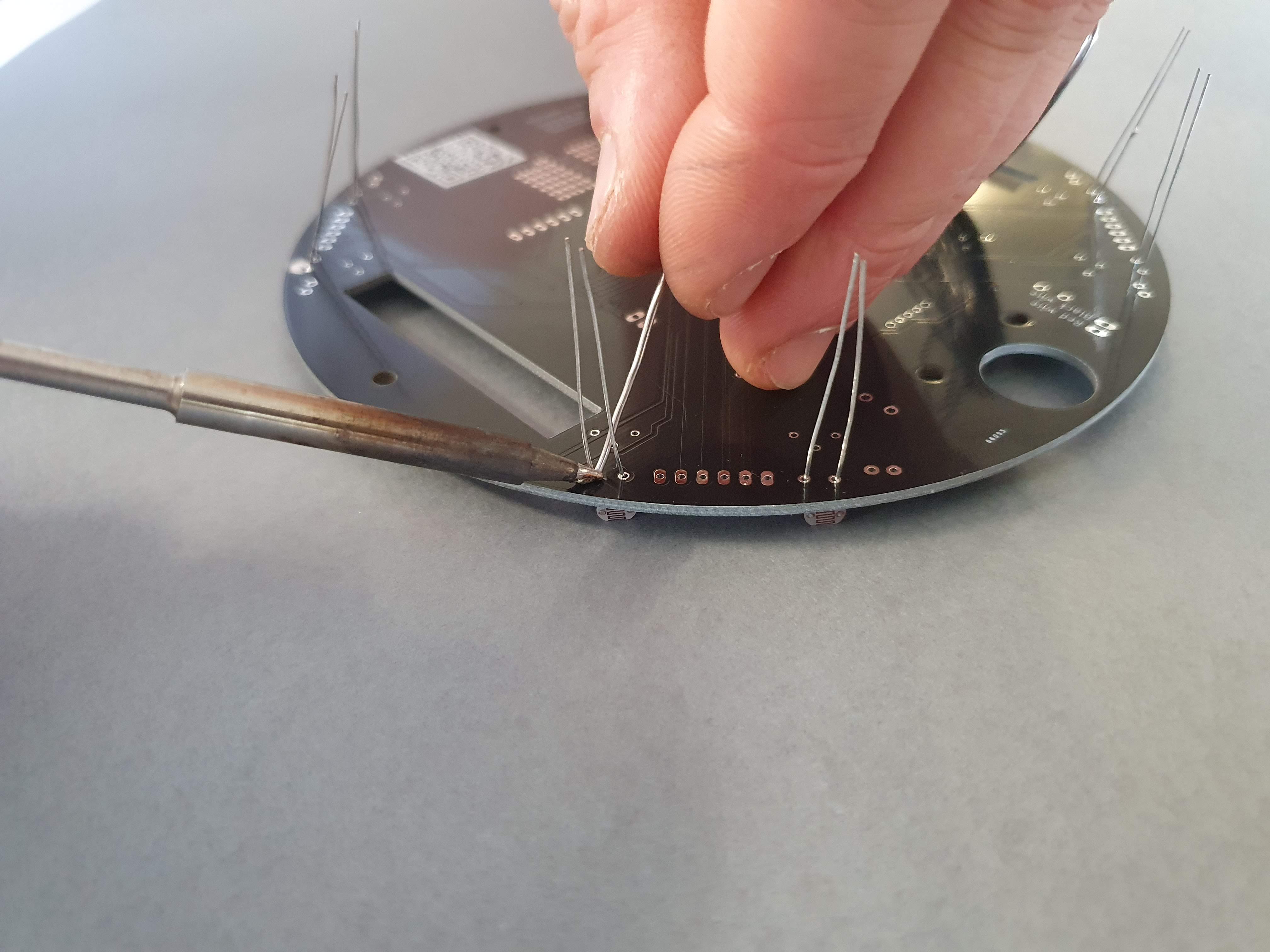
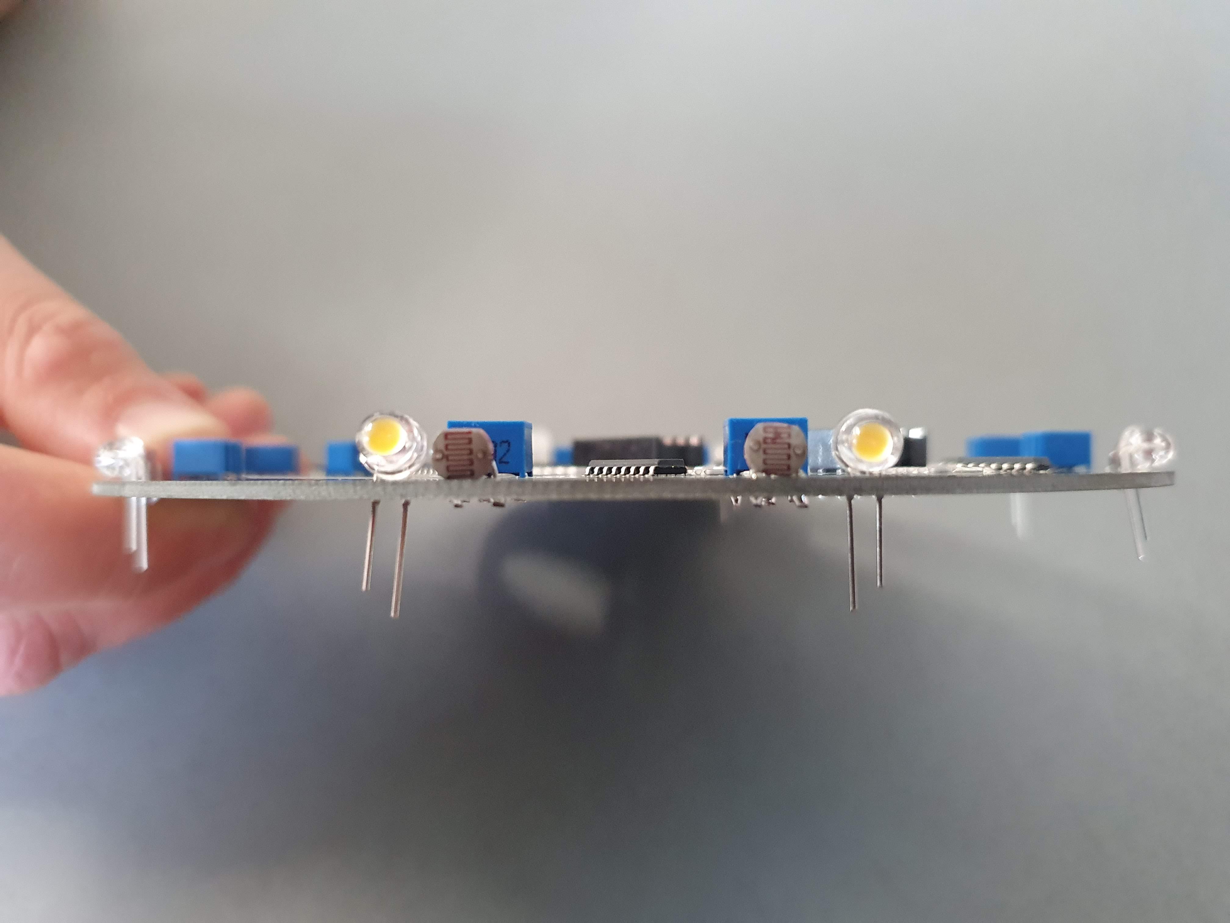
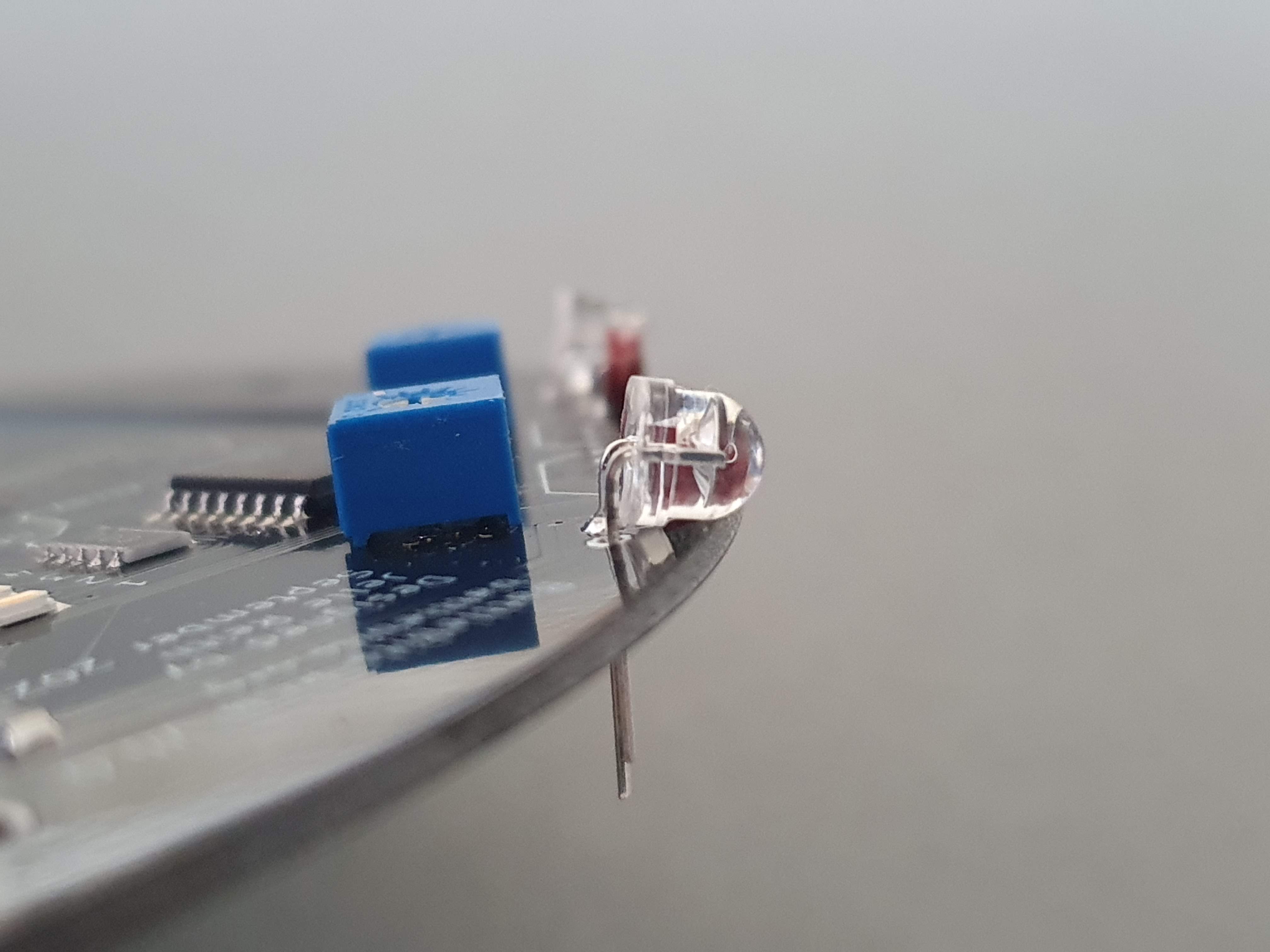
- 4: Flip the PCB over and check if the LDRs are flat on the pcb (if there is a gab you can reheat the solder joint and push the LDR through the holes a bit more
- 5: Solder the other legs
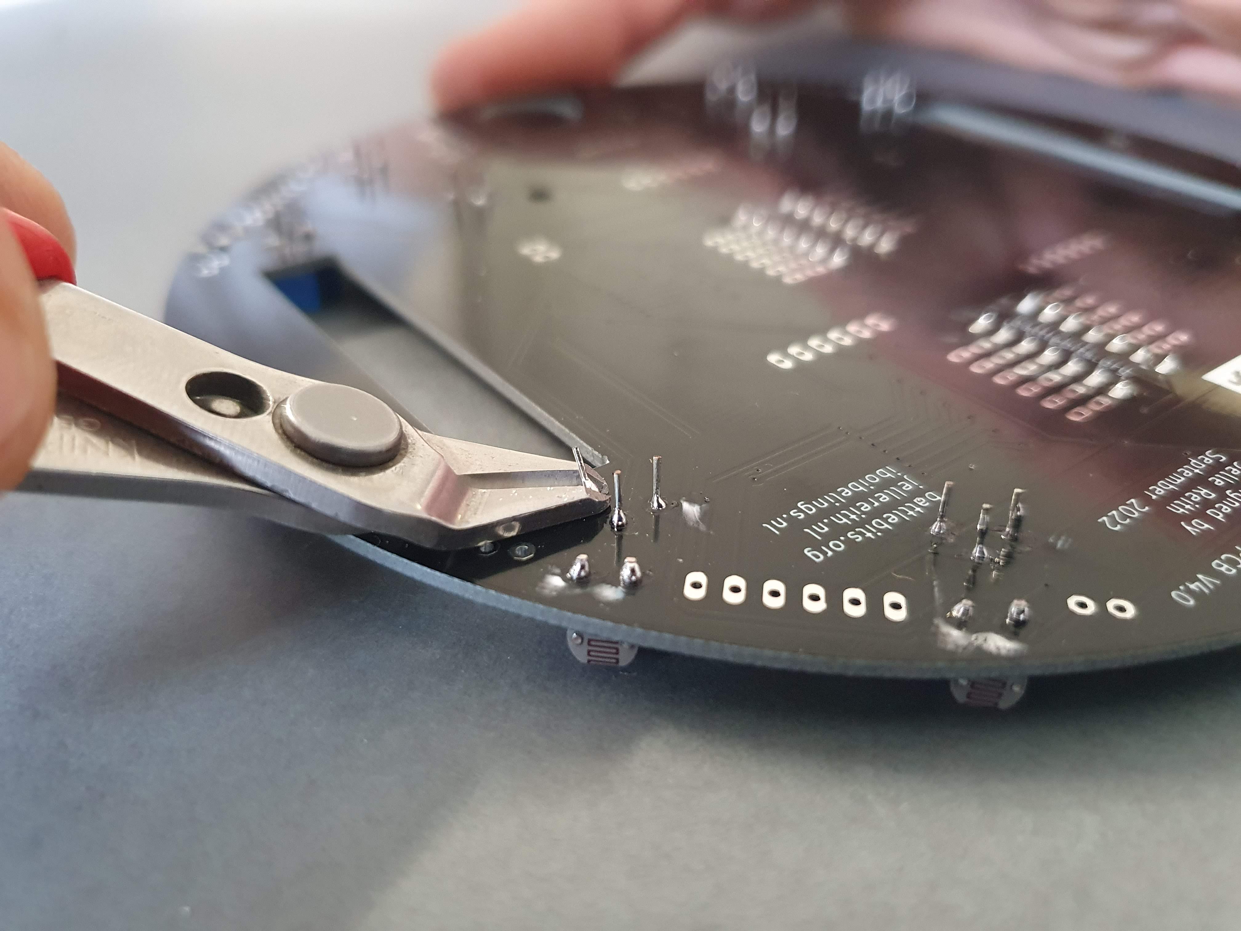
- 6: Trim the legs of the LDRs
Soldering DIP-14 sockets
In order the place the logic gates we need to install the ic sockets first. Different types of devices come in different types of physical appearances e.g. packages. The logic gates that we use have a are of the DIP (Dual-inline package) kind and have 14 pins. That's why we have to install a DIP-14 socket.
Materials:
- BattleBit PCB
- 2 x DIP-14 socket
Steps:
- 1: Place the sockets on the PCB. Make sure the notch of the socket is facing forwards
- 2: Solder two diagonal pins of the sockets (e.g. pin 1 and 8)
- 3: Check if the socket is laying flat on the PCB
- 4: Solder all other pins
Soldering the 10 Potentiometers
Materials:
- BattleBit PCB
- 10 x 20k potentiometer
Steps:
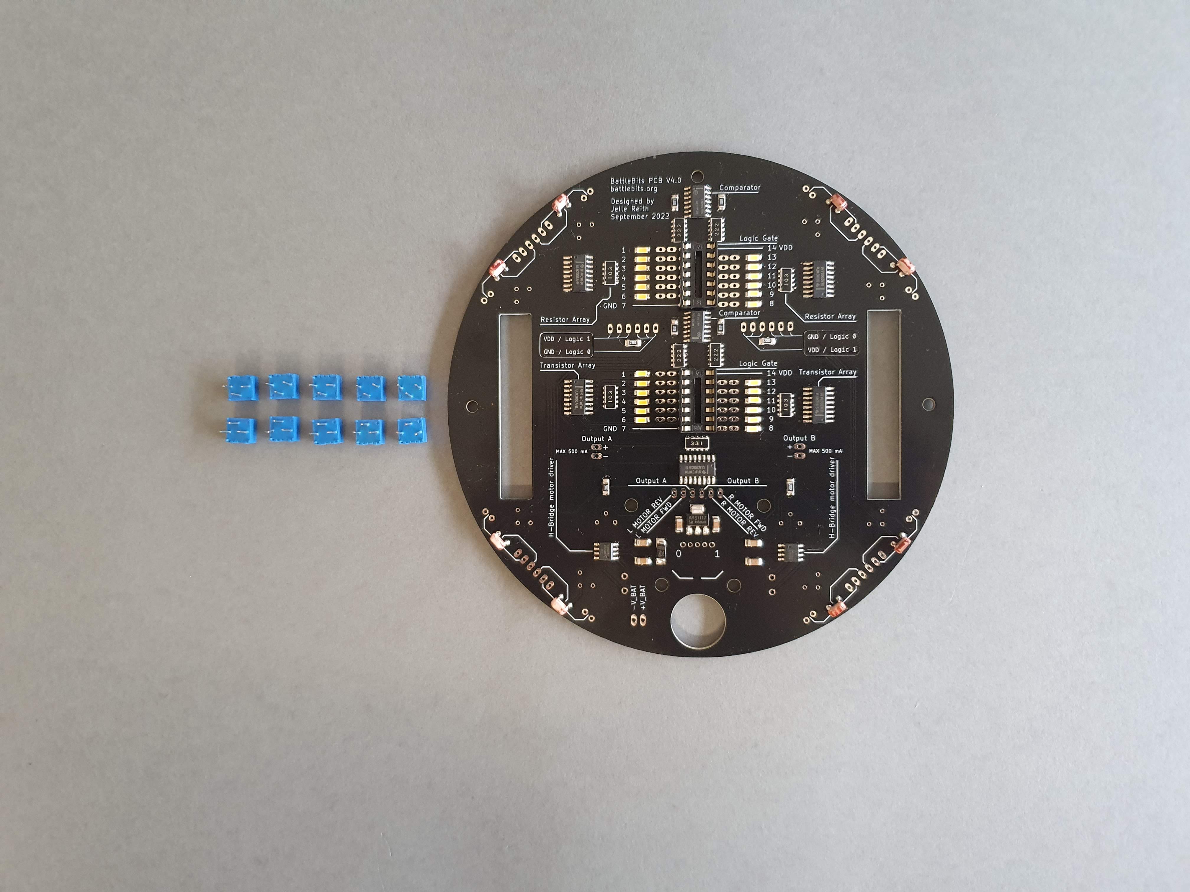
- 1: Place the potentiometers in the following way:
- 2: Flip the PCB aroud using a piece of wood / cartboard
- 3: Solder one of the legs of each potentiometer
- 4: Flip around and check if all the potentiometers are laying flat on the PCB
- 5: Rotate the PCB and solder the rest of the legs
- 6: Trim the legs of the potentiometers
Soldering the LEDs (Light Emitting Diodes)
Light Emitting Diodes are a type of diode that emit light when a current is passed through the device. In contrast to incandescent light sources the resistance of a LED decreased when the temperature increases. To use a LED we either need to use a constant current source or we need to place a resistor in series with the LED. We also need to consider that a LED has a polarity. The longest leg of the LED is the anode, meaning that it should be connected to the positive side of the circuit. The shortest leg of the LED is the cathode and needs to be connected to the negative side of the circuit.
Materials:
- BattleBit PCB
- 8 x LED
Steps:
- 1: Bend the legs of the LEDs, 4 with the cathode and 4 with the anode on the right
- 2: Place the LEDs on the PCB as shown on the picture. Make sure the polarity is correct!
- 3: Solder one pin of each LED
- 4: Check if the LEDs are laying flat on the PCB and solder the rest of the pins
- 5: Trim the legs of the soldered LEDs
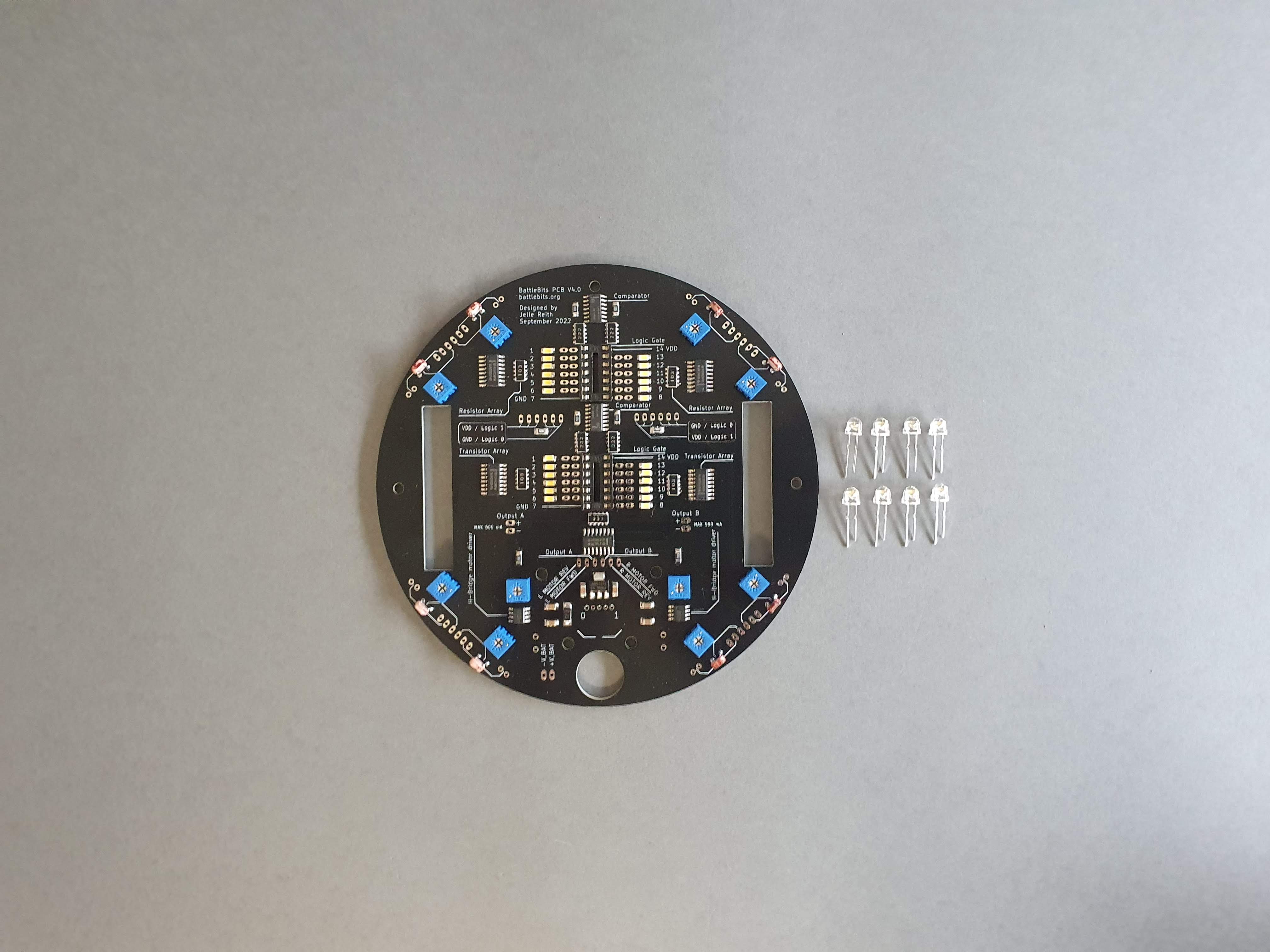
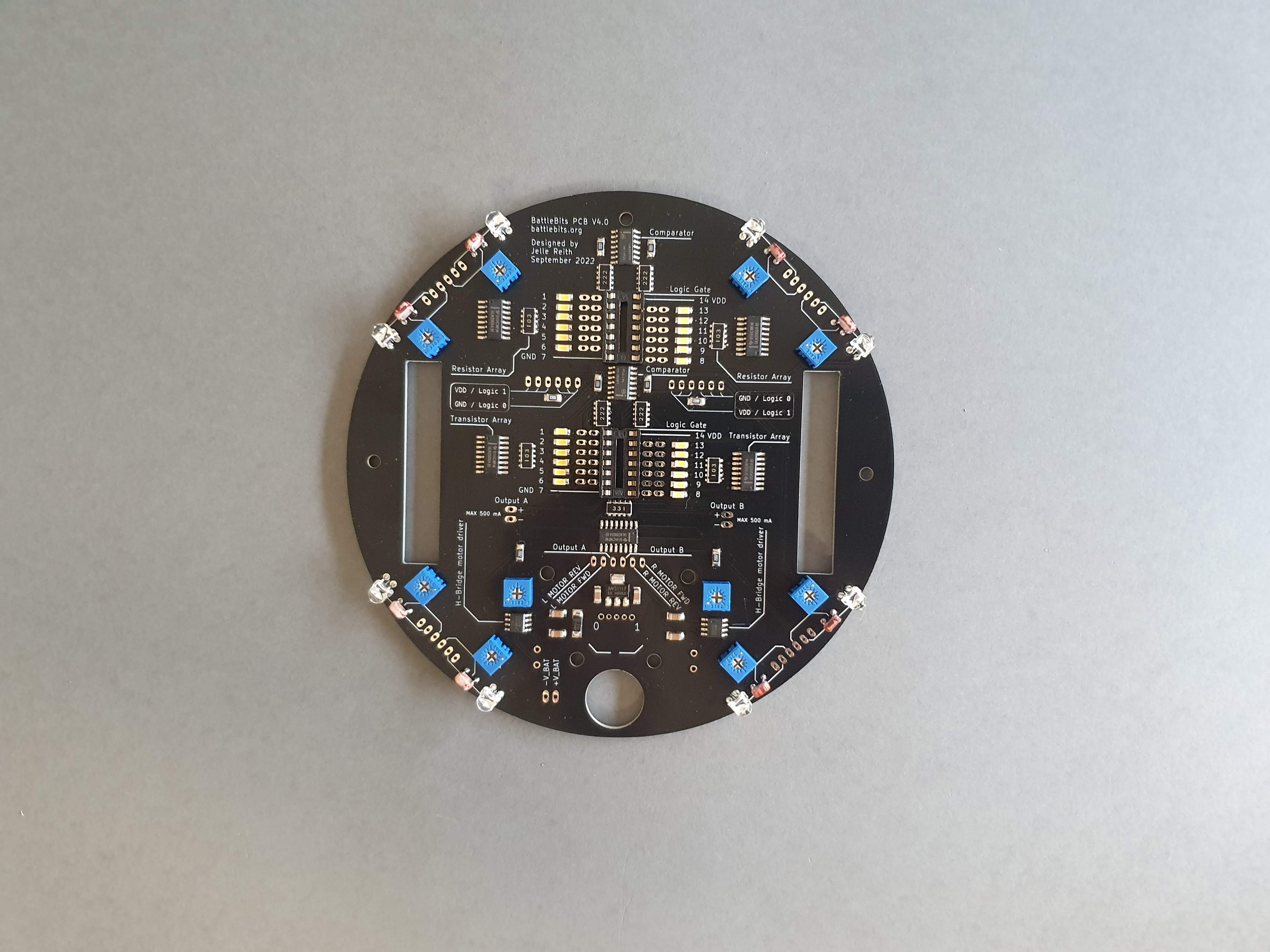
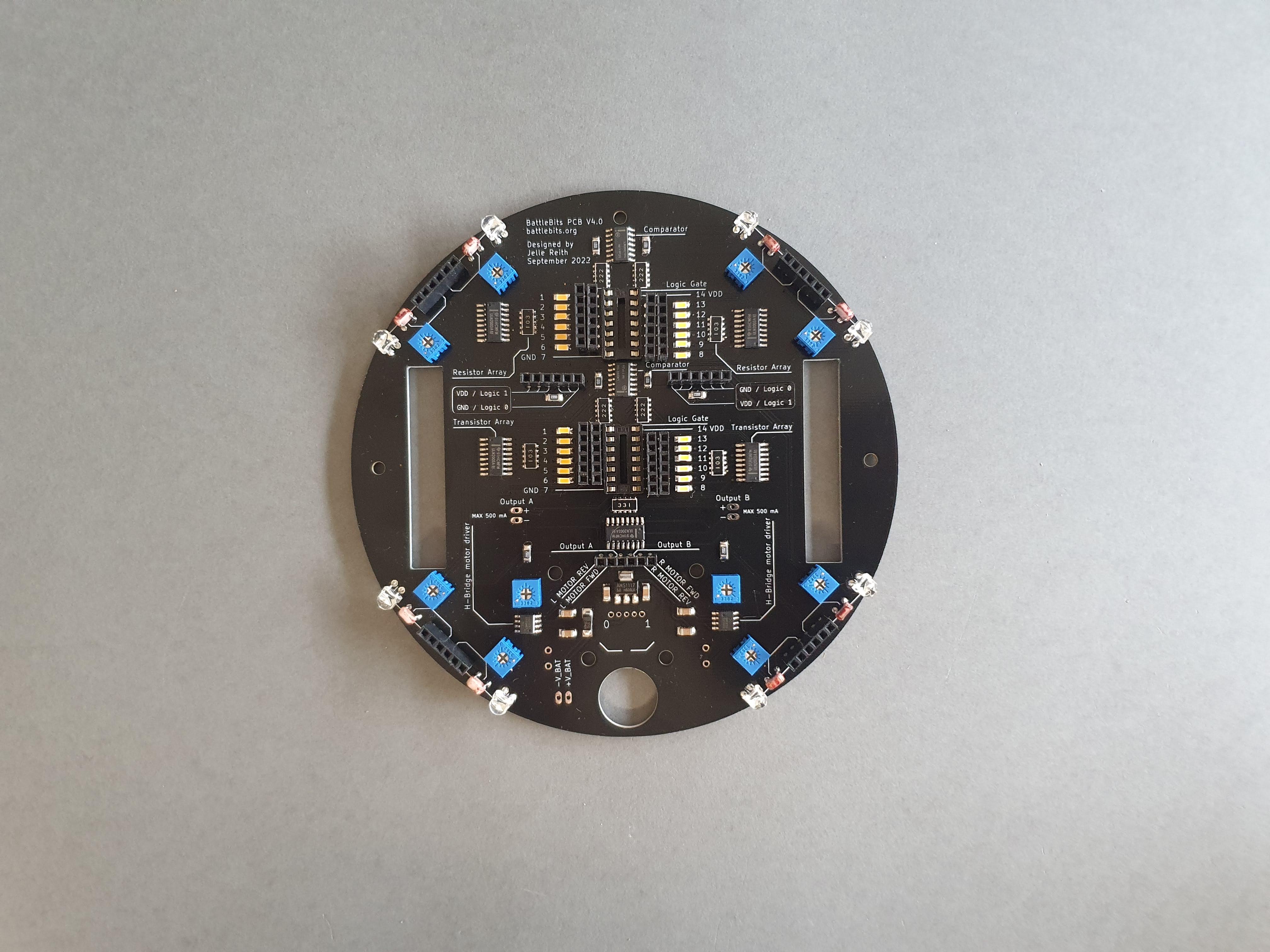
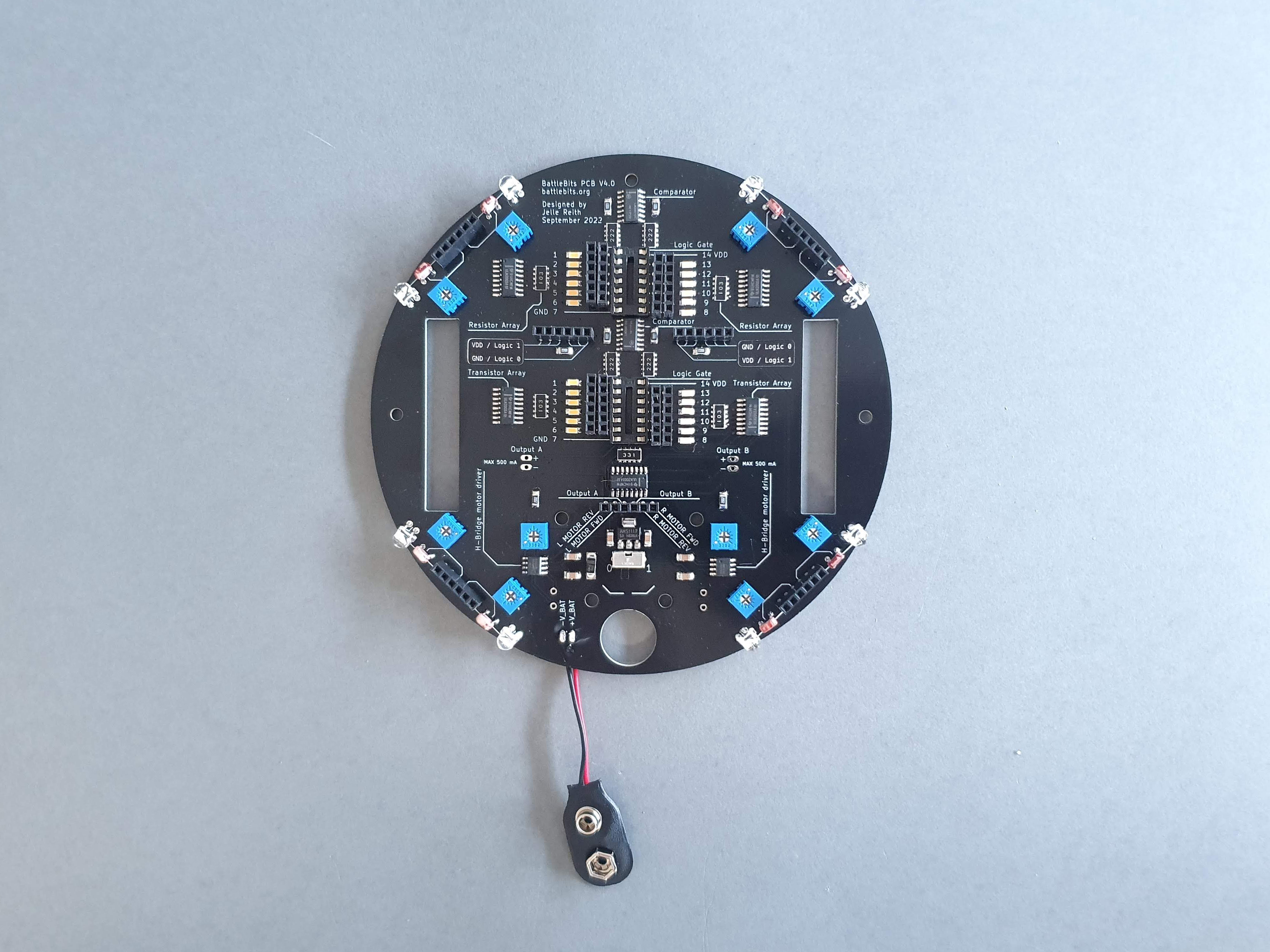
- 6: Now make sure your board looks like this:
Soldering the pin headers
Pinheaders are often used to make connections between different PCBs or between different parts of a circuit. The pinheaders of the BattleBit PCB allow you to make connections between the in- and outputs of the logic gates and thus allow you to program the PCB.
Materials:
- BattleBit PCB
- 15 x 6 pin female headers
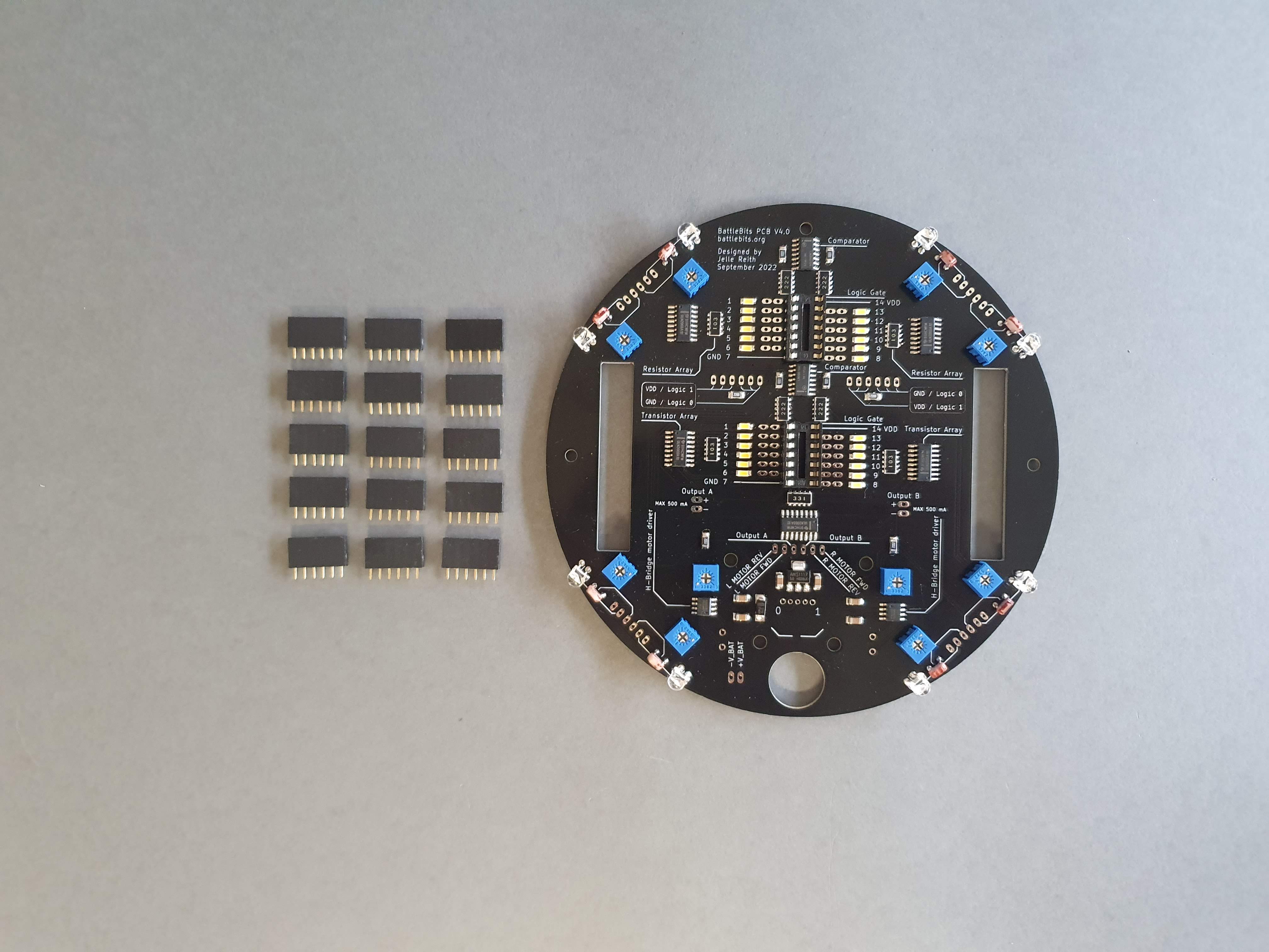
Steps:
- 1: Place all 15 headers
- 2: Flip the PCB upside down. With the same technique as with the potentiometers. If you place something flat on top of the PCB and press it down while you flip the PCB upside down the headers won't fall out
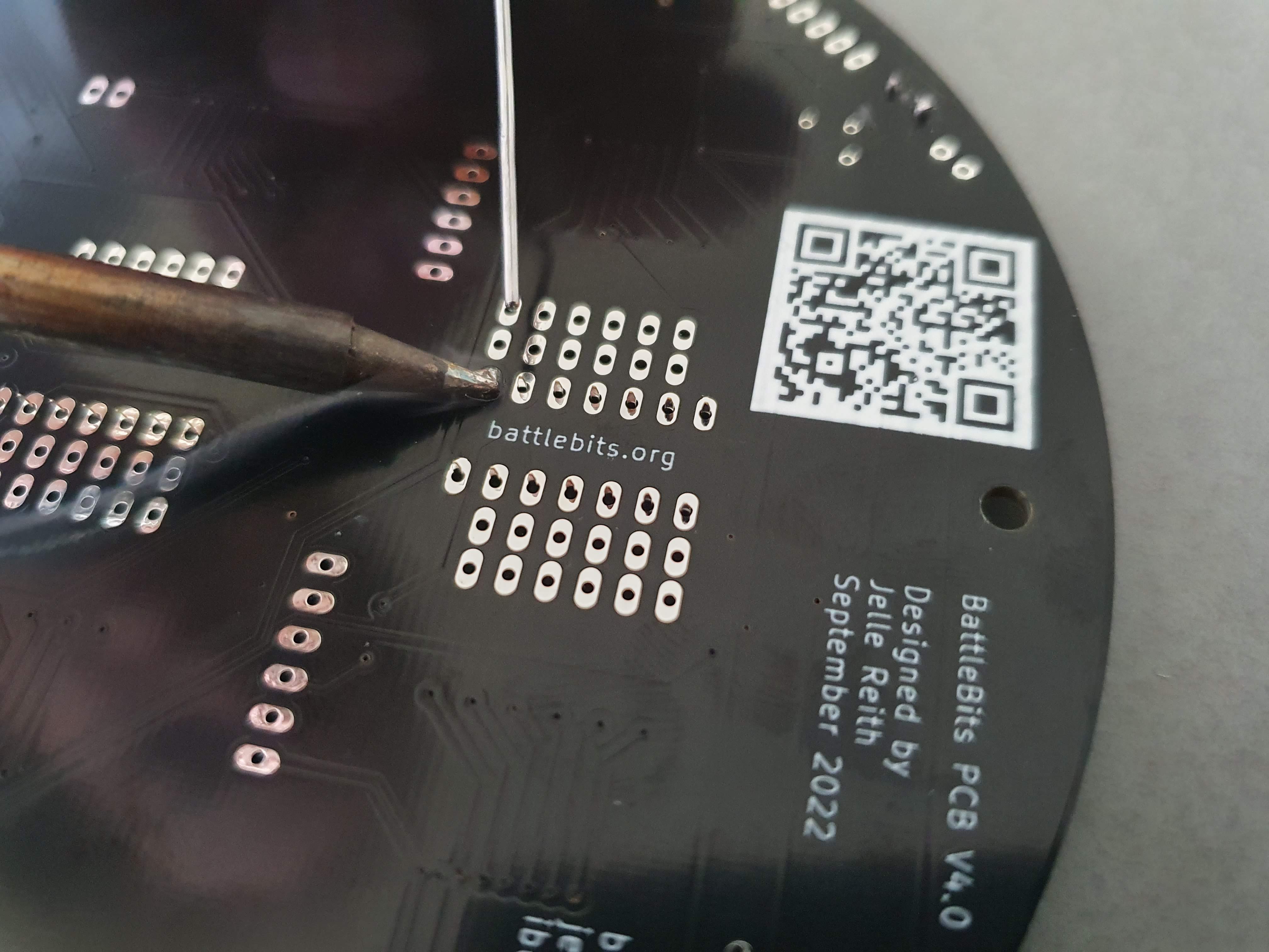
- 3: Solder one pin of each header
- 4: Check if all headers are perpendicular to the PCB
- 5: Solder all other pins
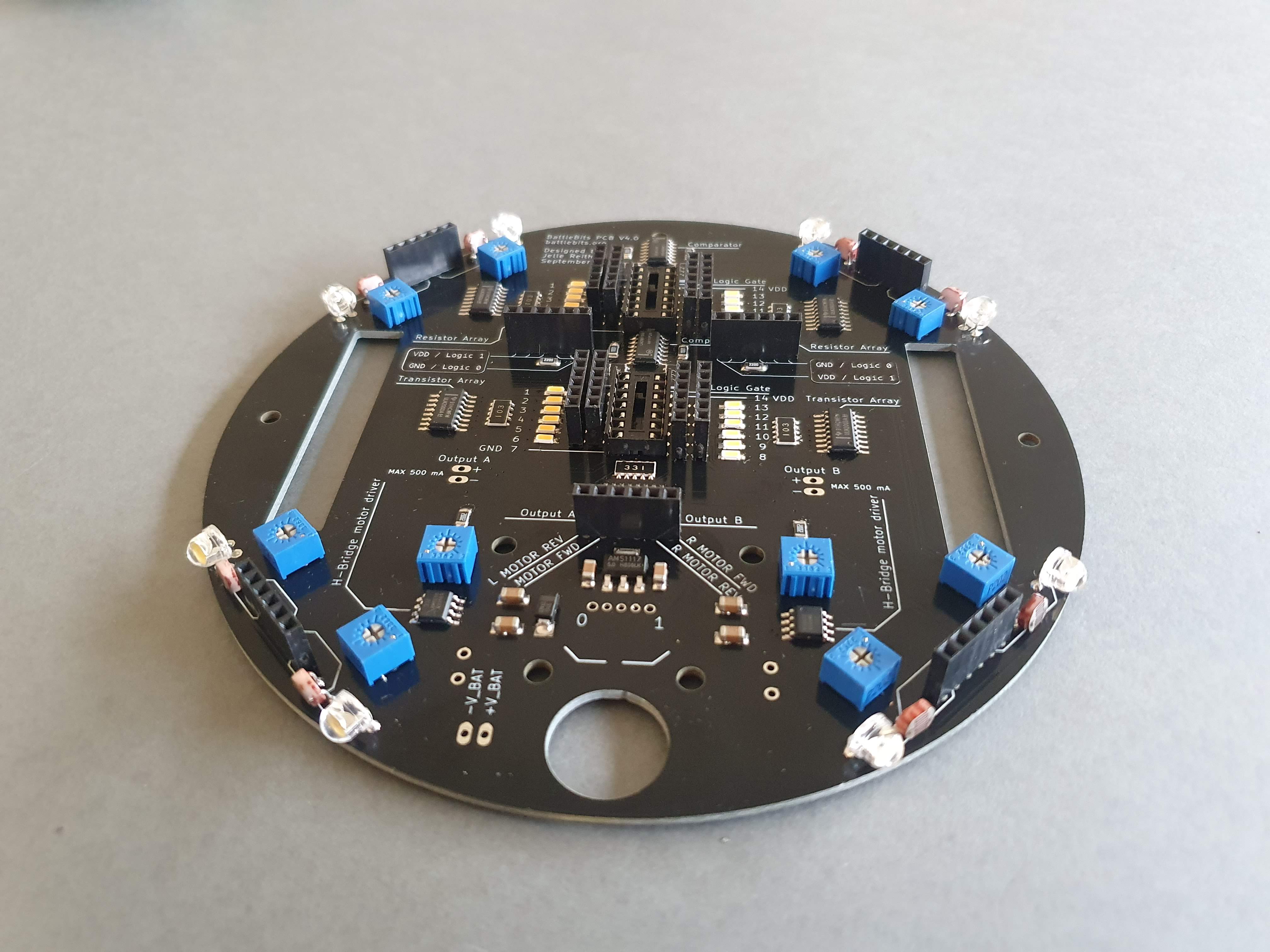
- 6: Now the board should look like this:
Soldering the on/off switch
Materials:
- BattleBit PCB
- 1 x on/off switch
Steps:
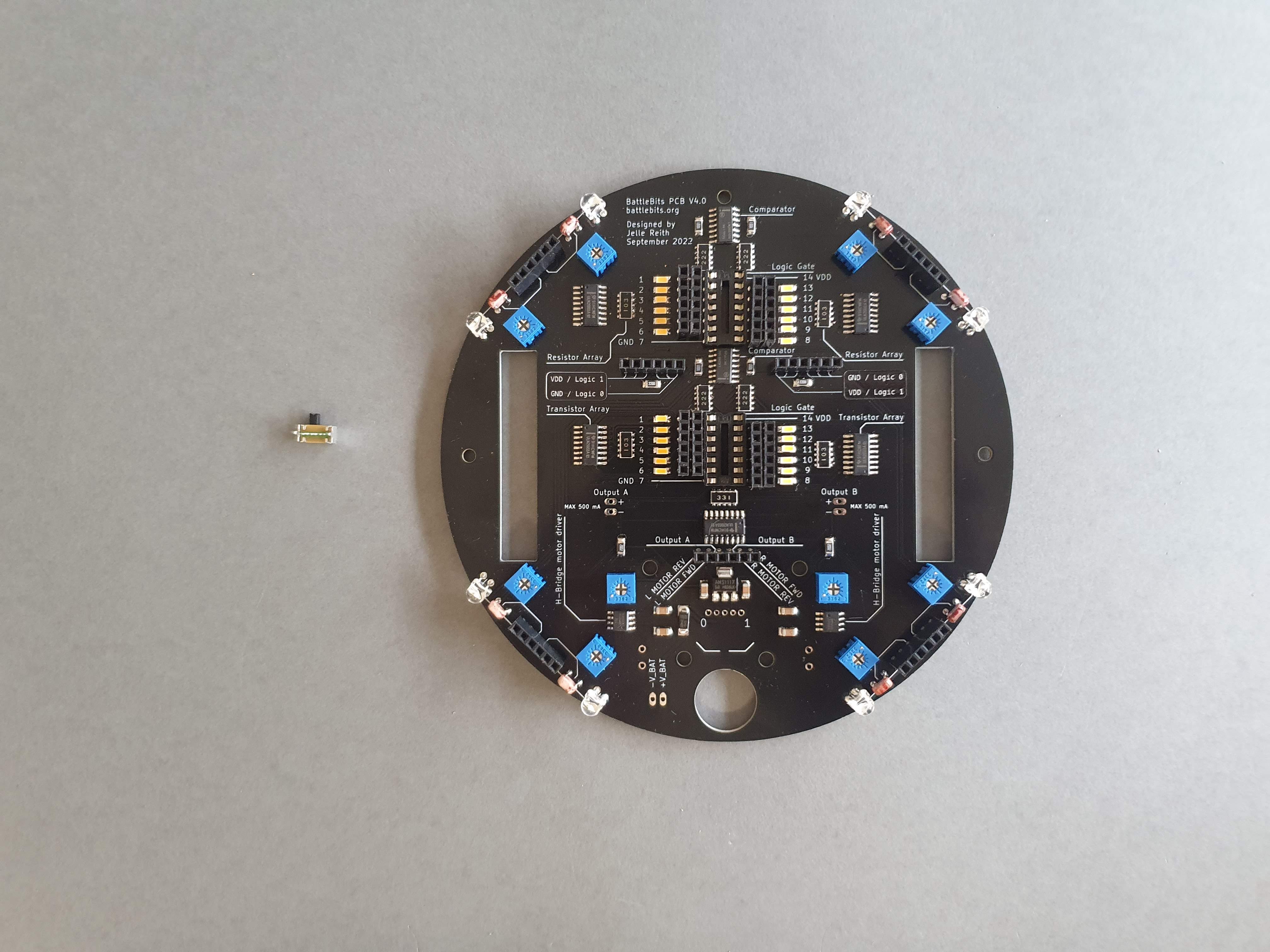
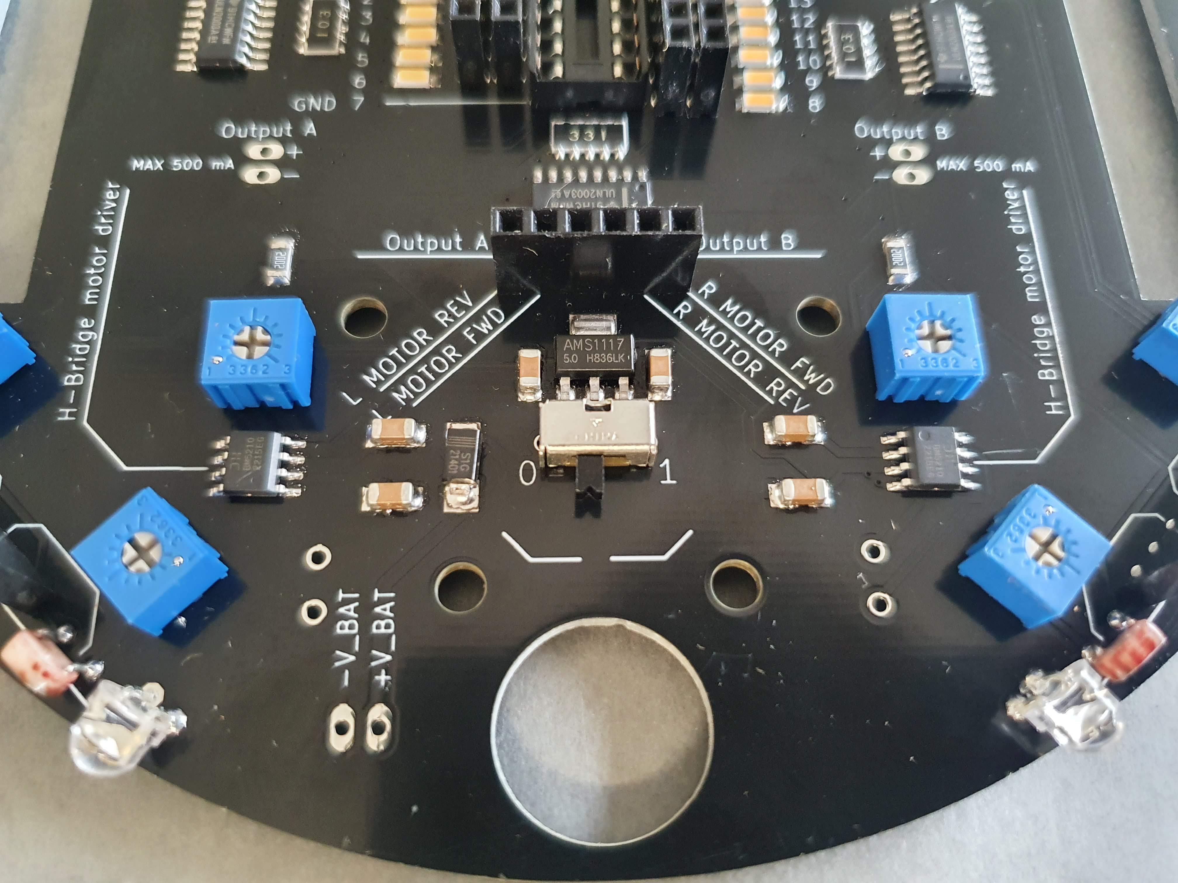
- 1: Place the switch:
- 2: Solder the pins on the board
9v battery connector
Materials:
- BattleBit PCB
- 1 x 9v battery connector
Steps:
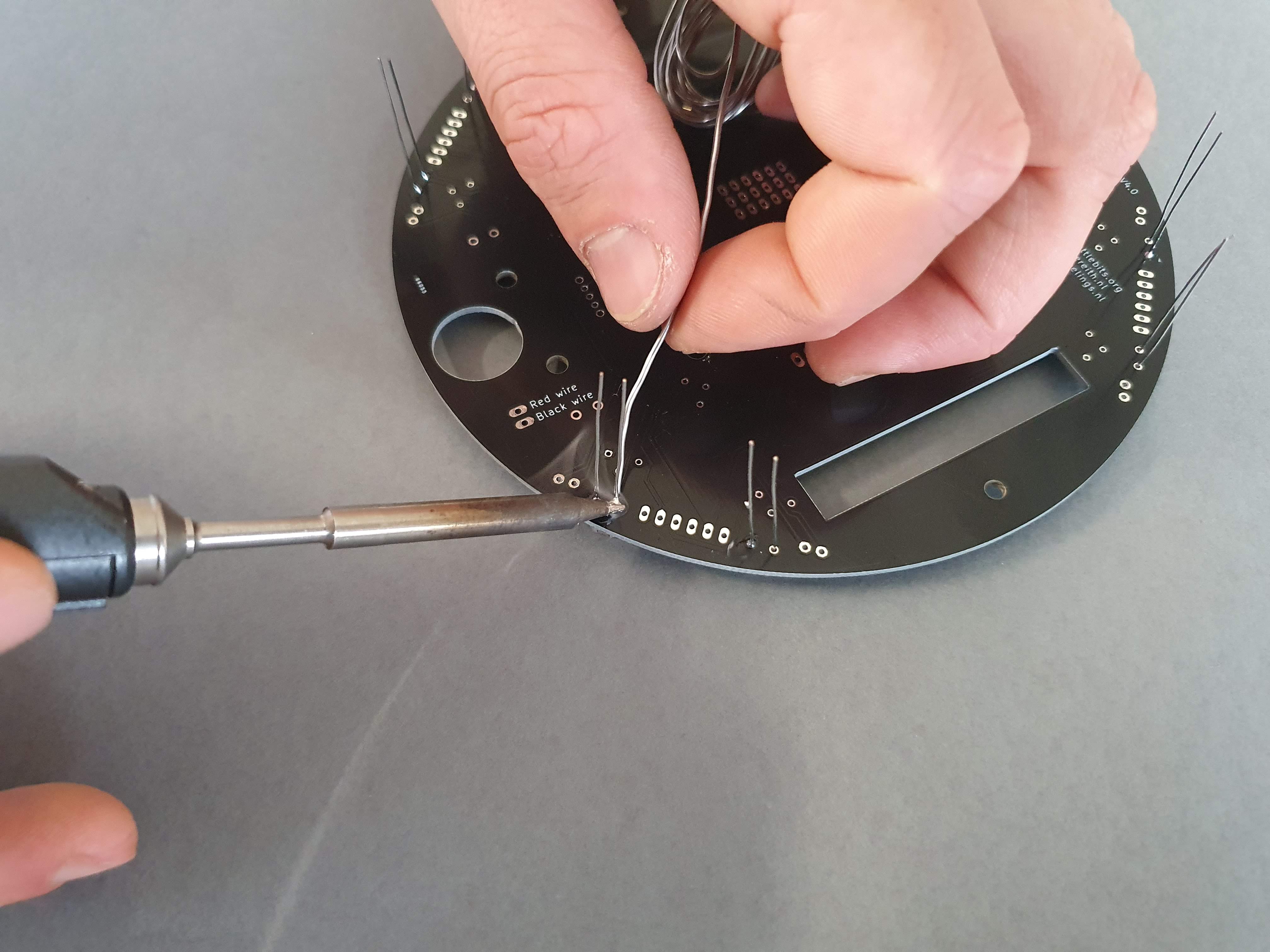
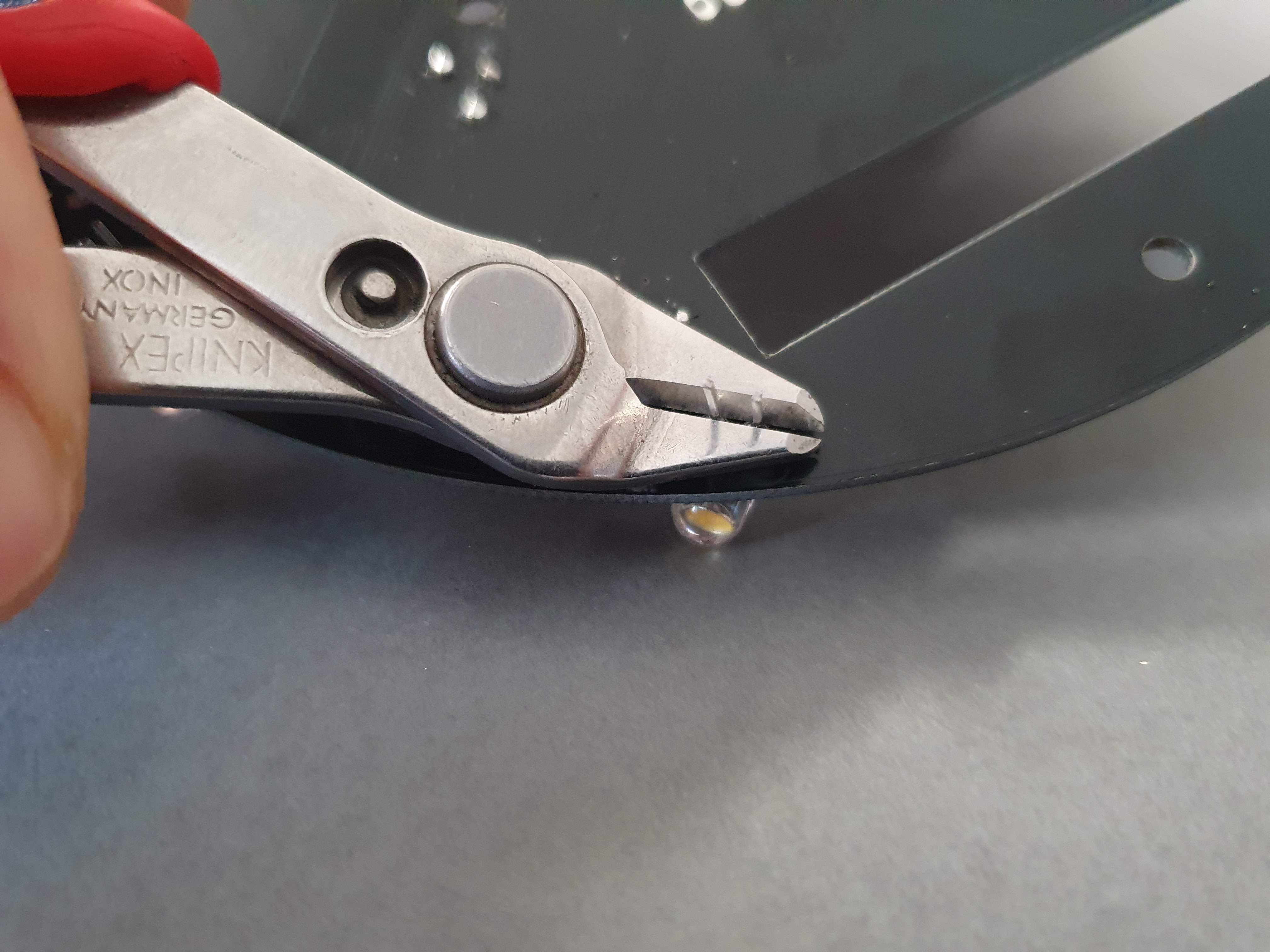
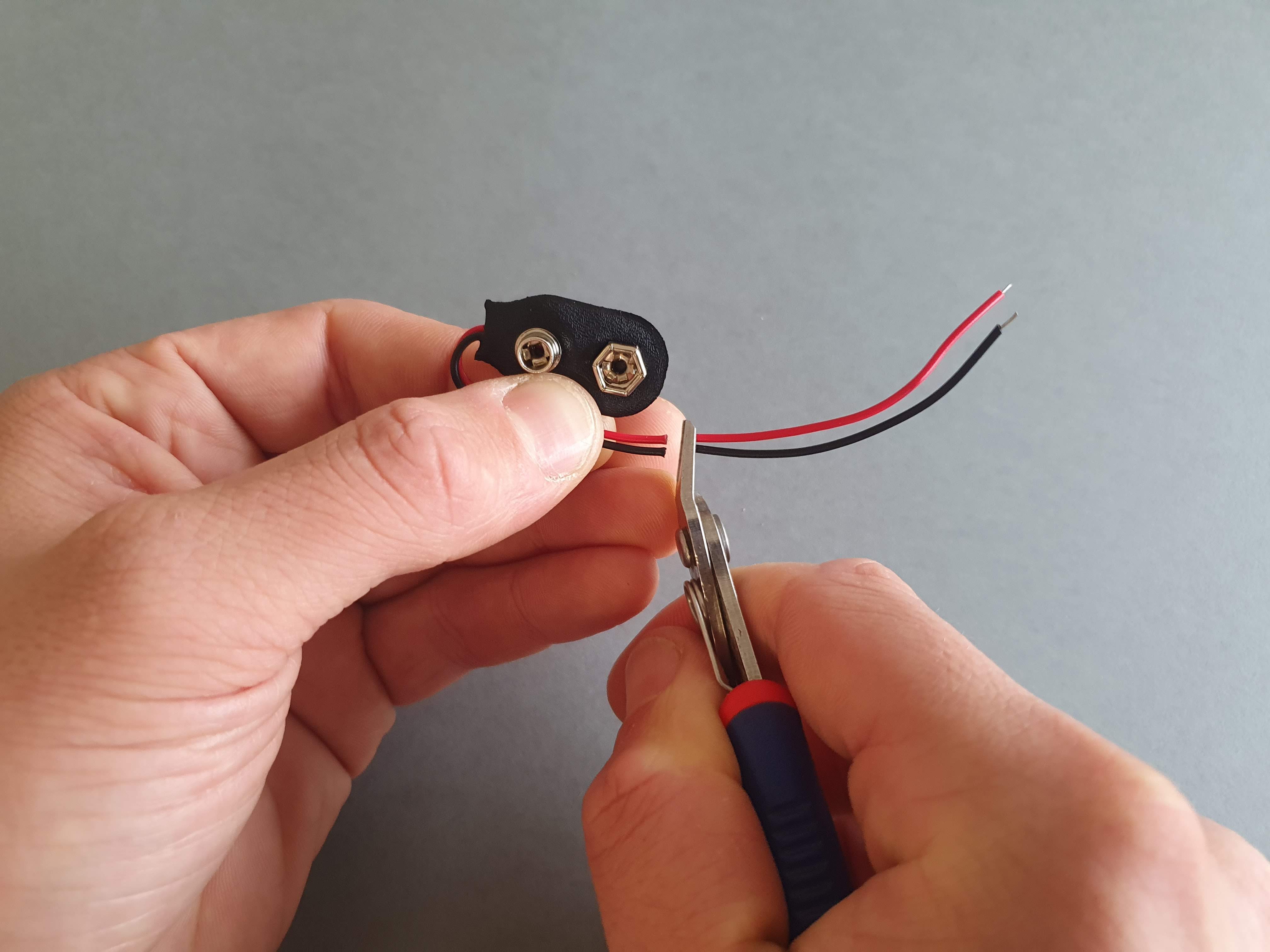
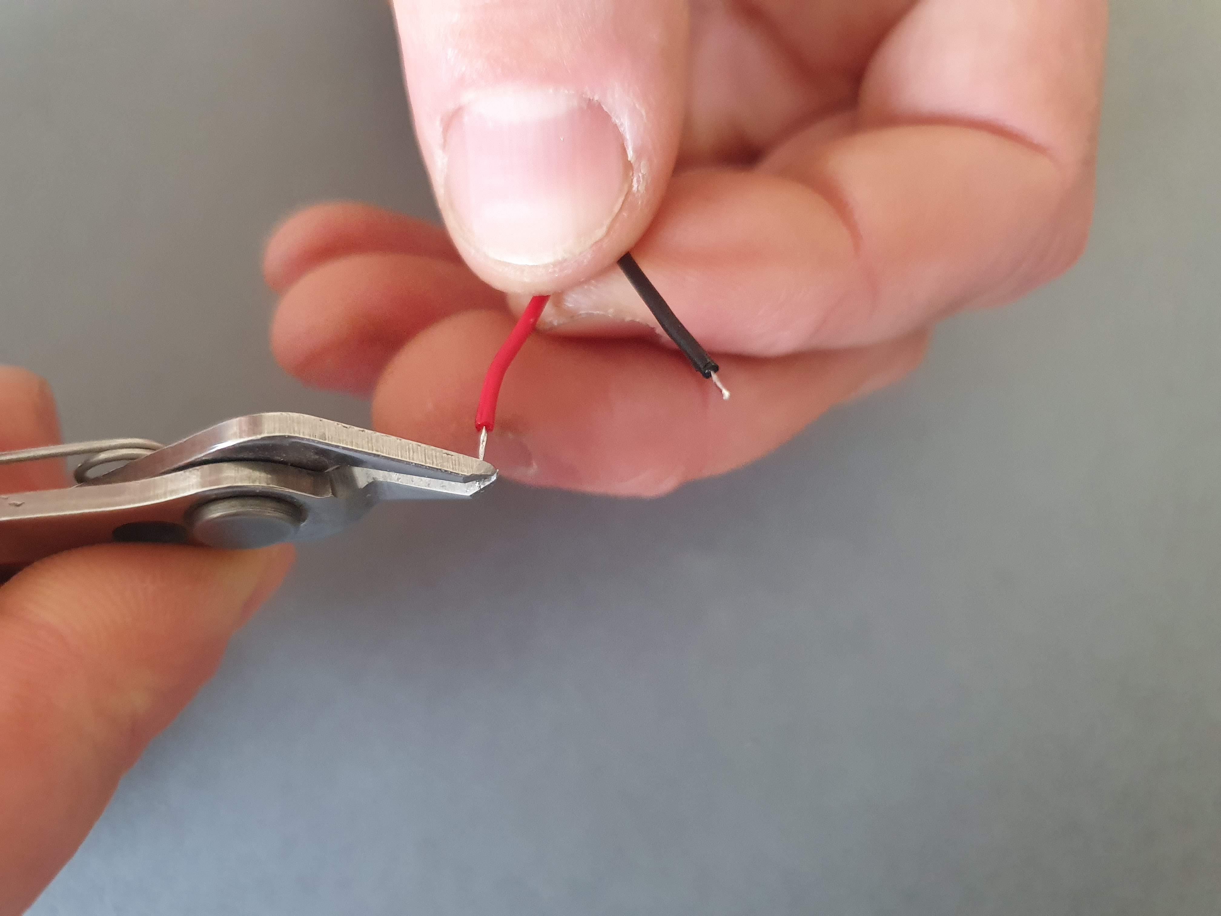
- 1: Bend the cable of the connector as shown on the image
- 2: Cut the wires as shown on the image
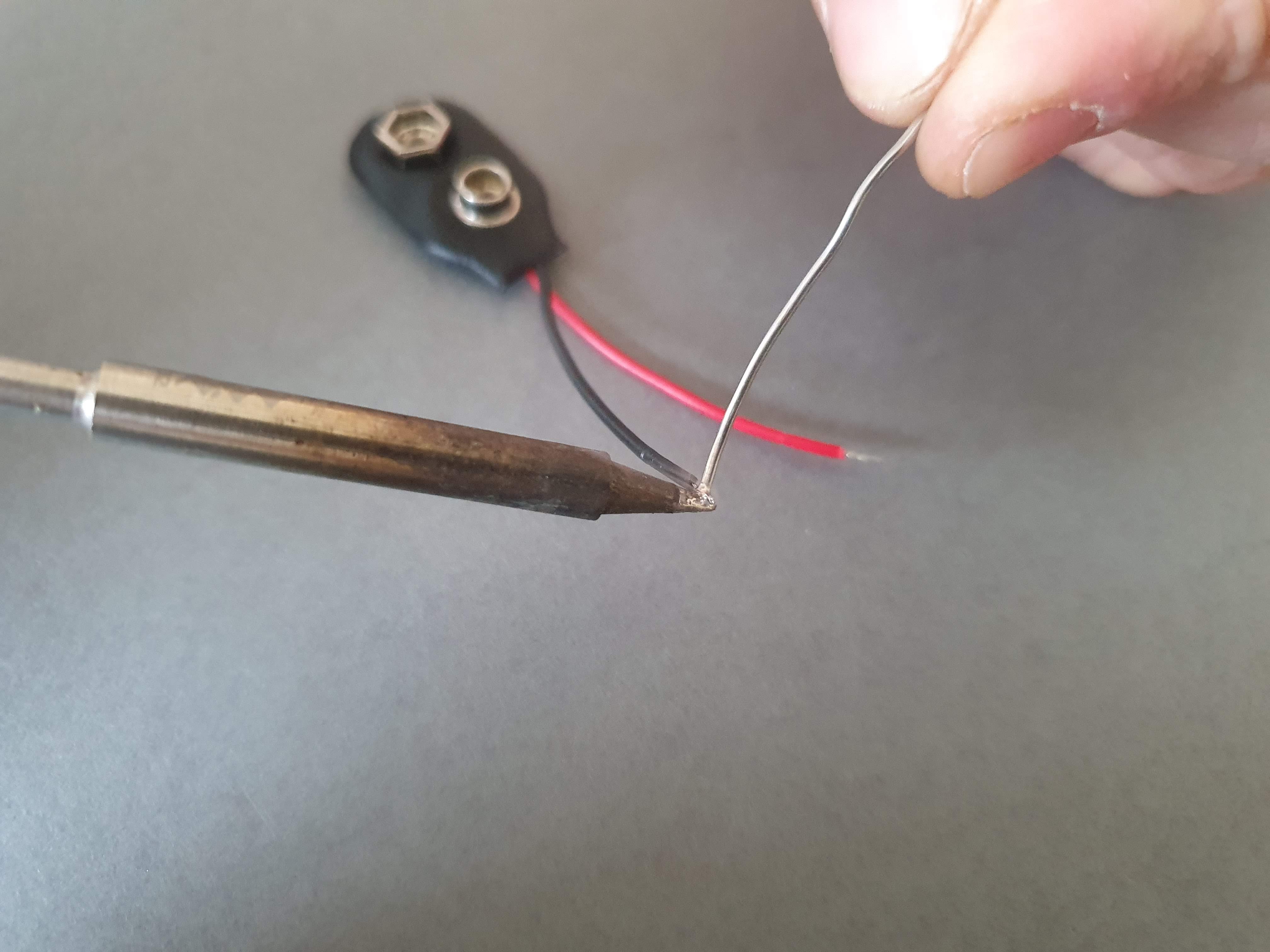
- 3: Strip the ends of the wires
- 4: Apply a little bit of soldering tin on the exposed ends (this process is called tinning) & remove any extra exposed wire
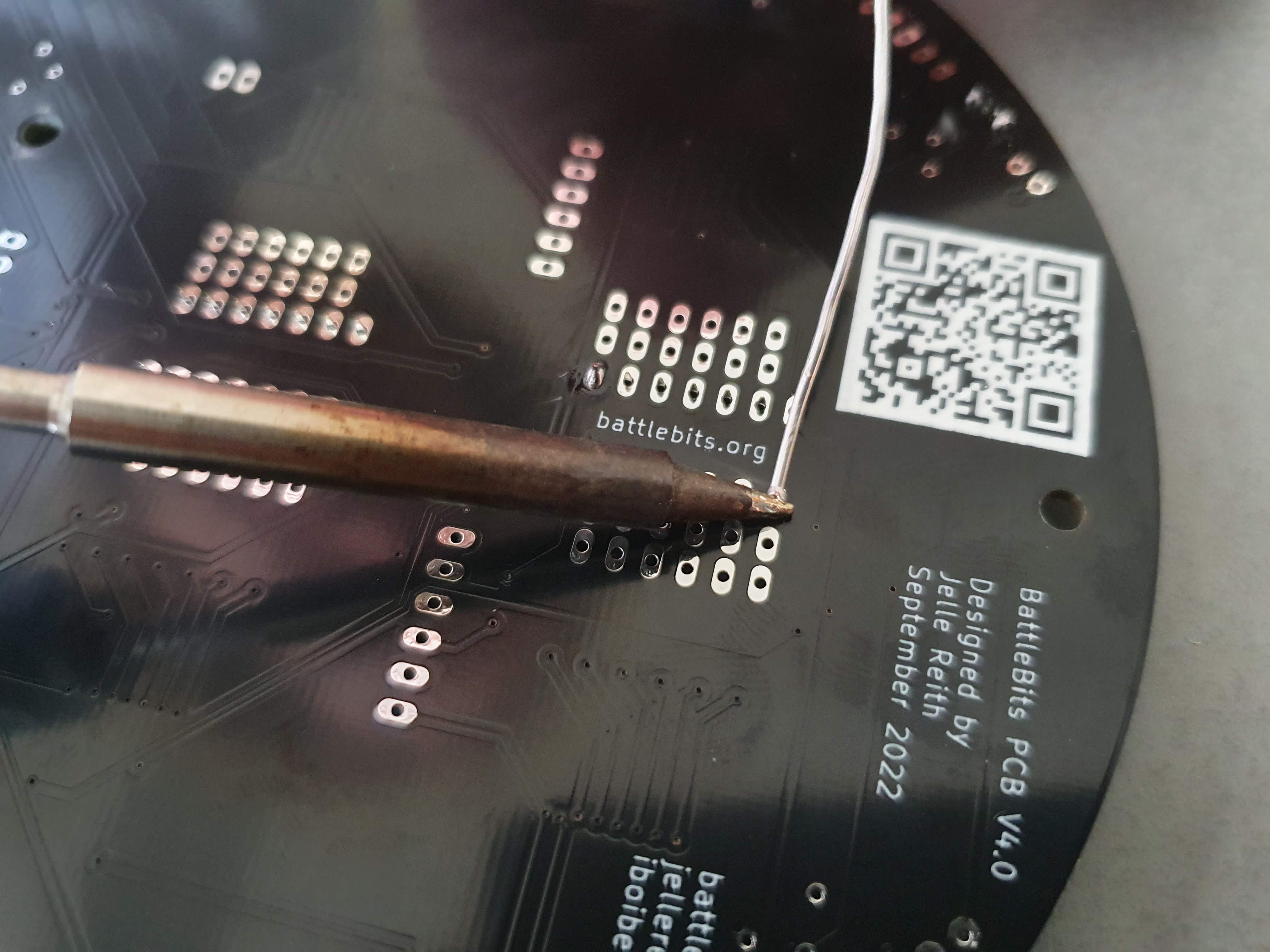
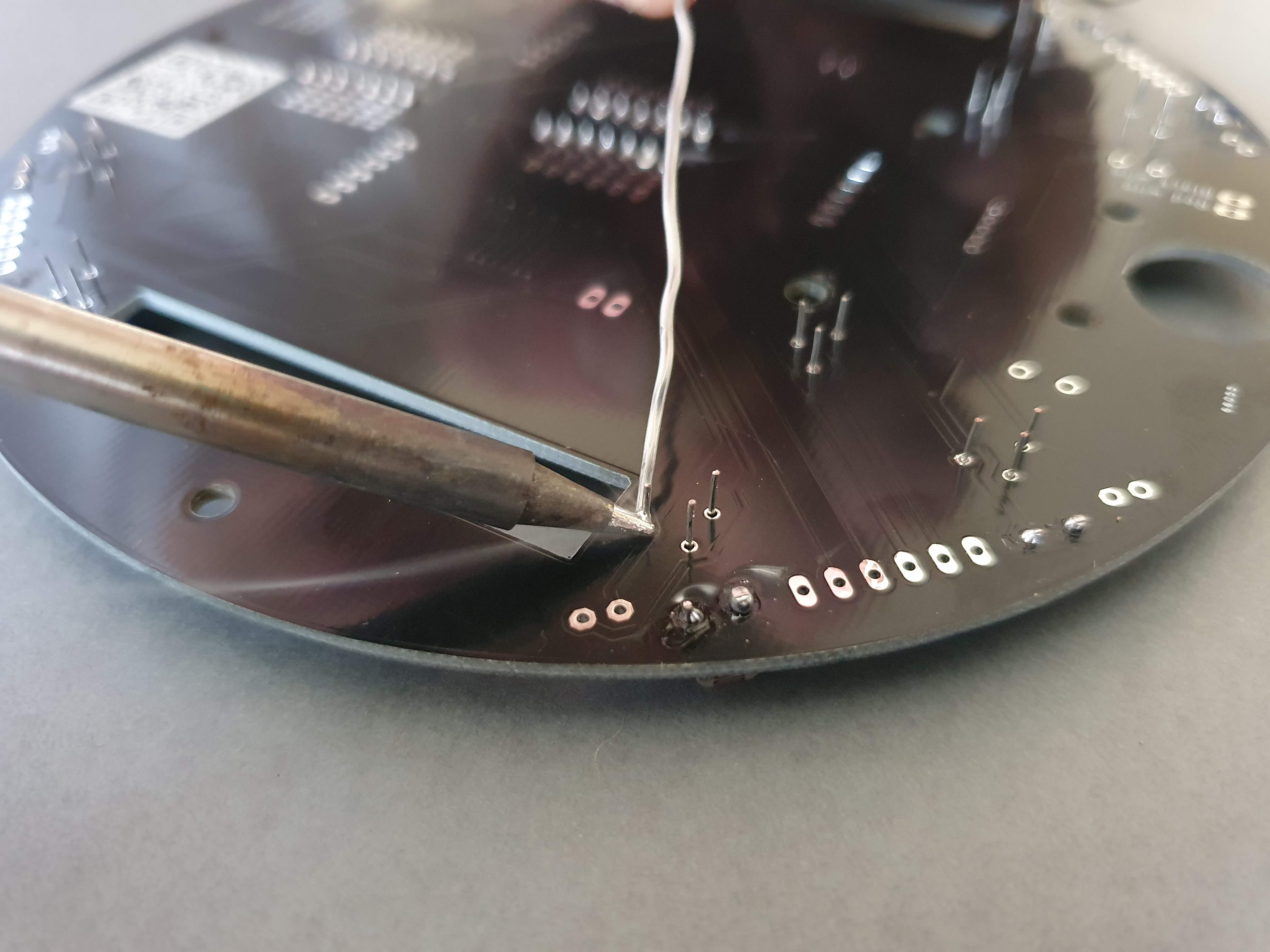
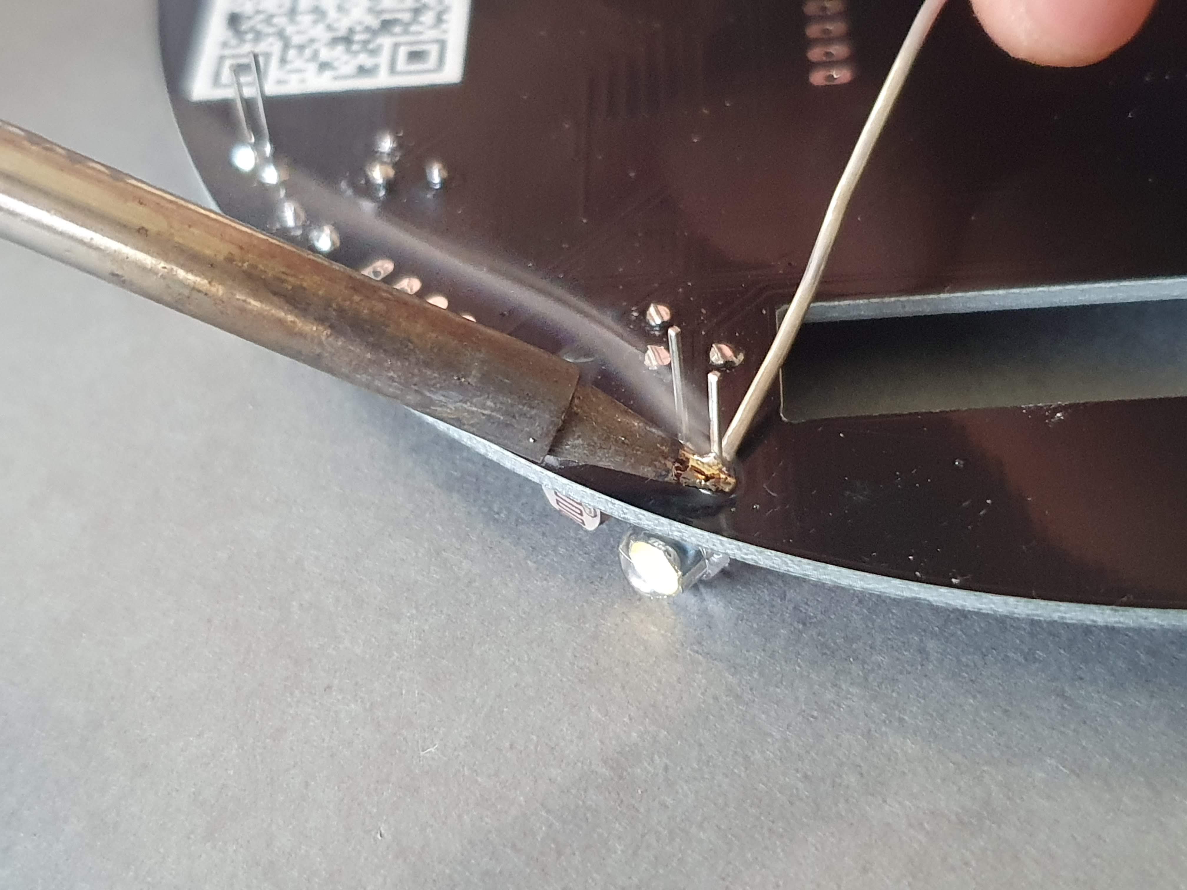
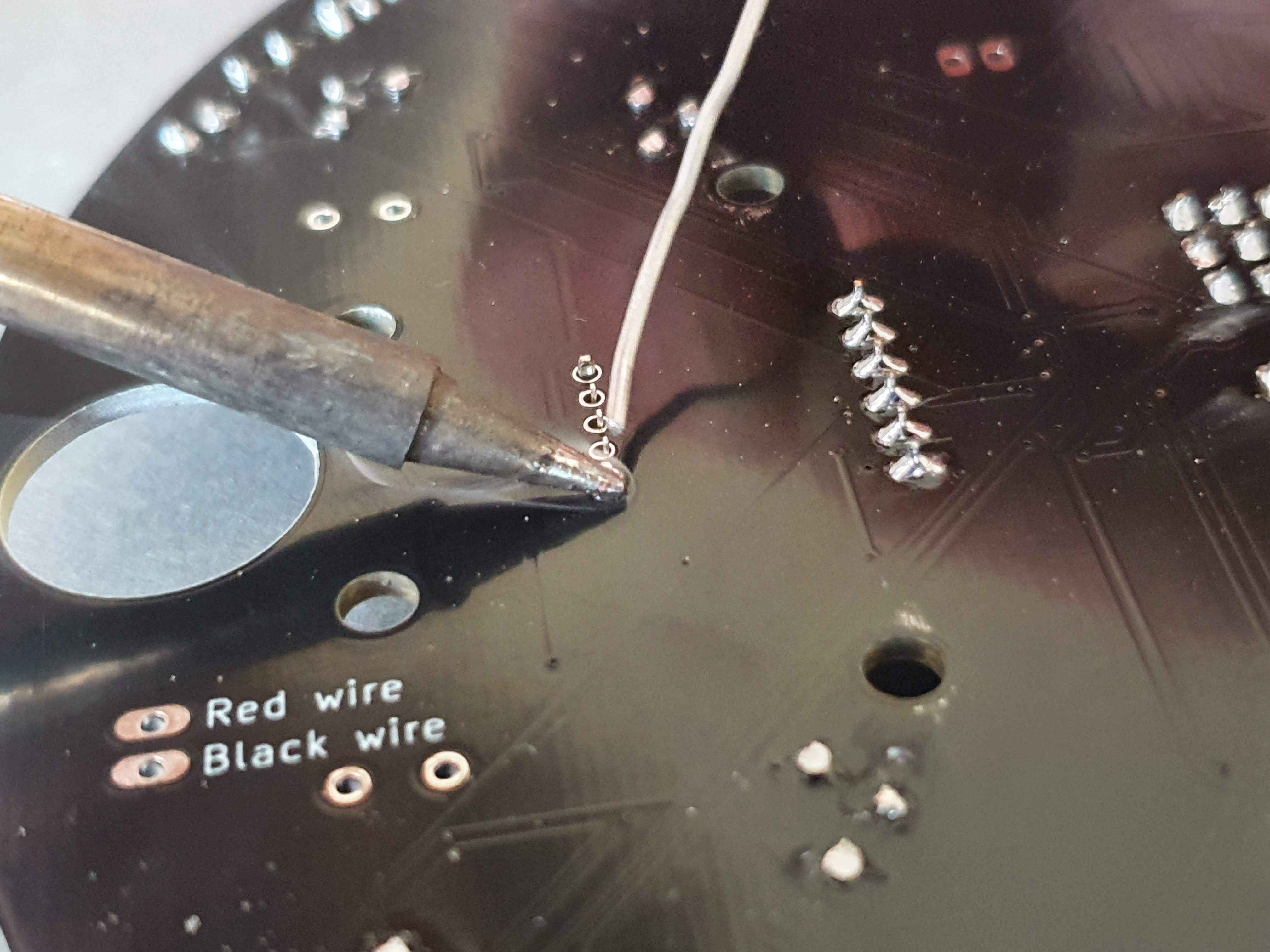
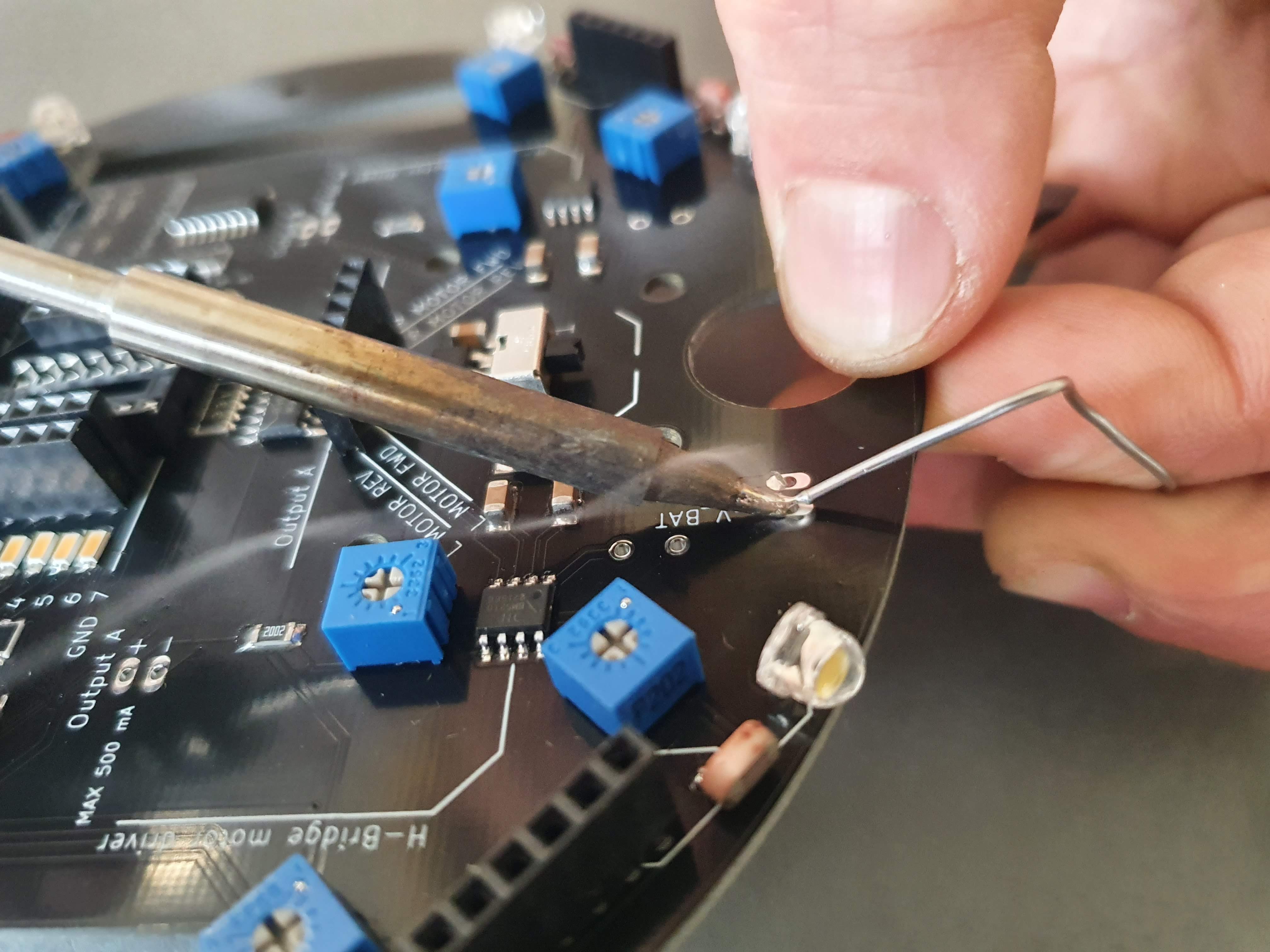
- 5: Push the exposed ends through the holes on the PCB (indicated by 'red wire' and 'black wire' label)
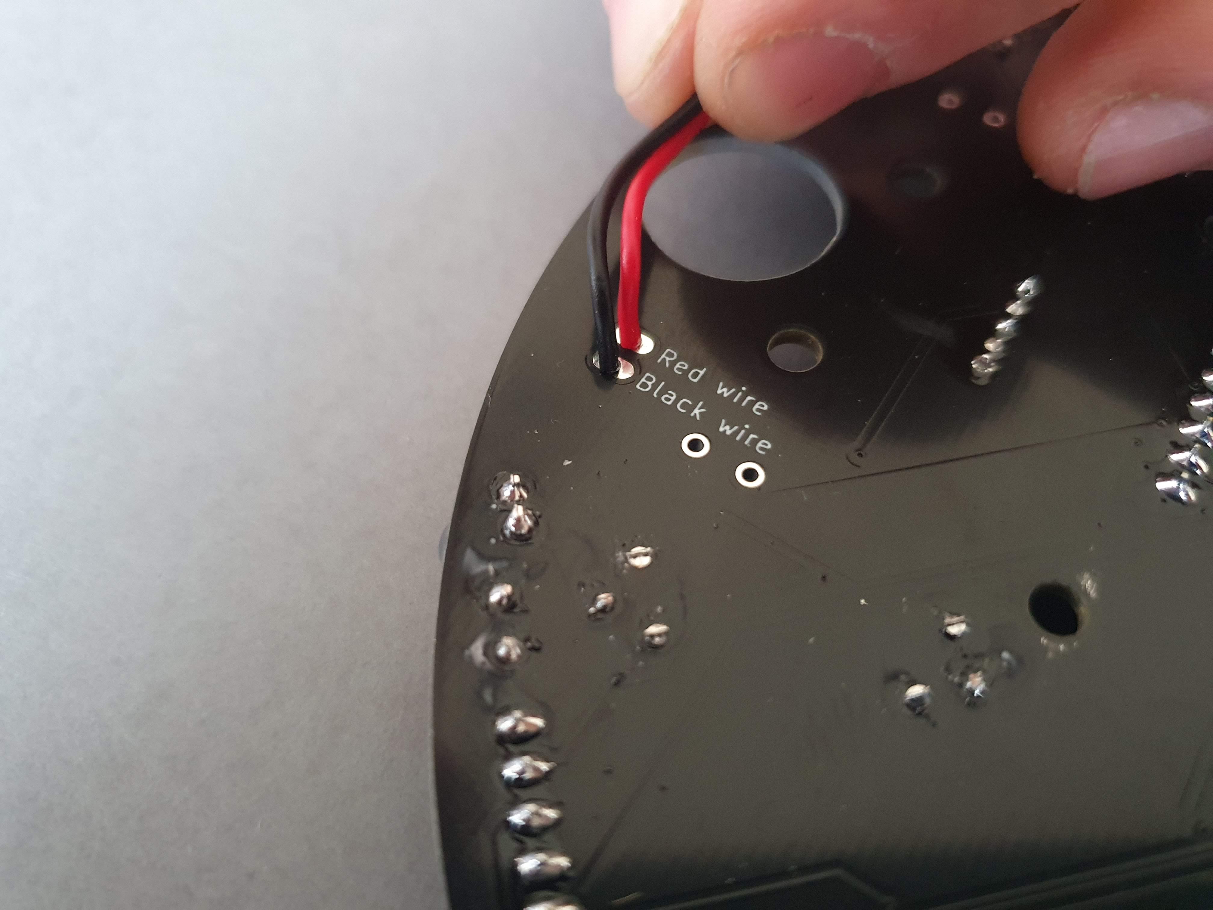
- 6: Solder the wires to the PCB
- 7: Your board should now look like this:
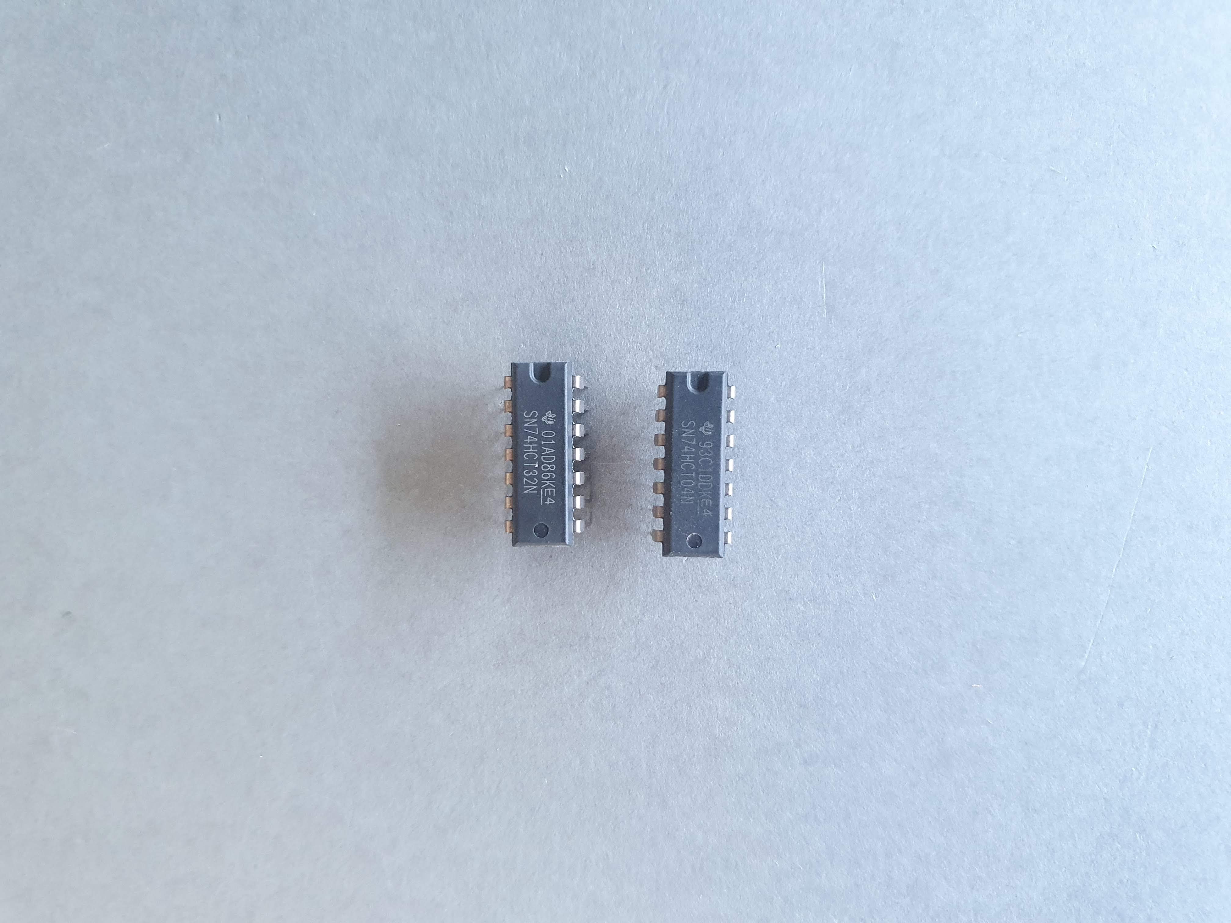
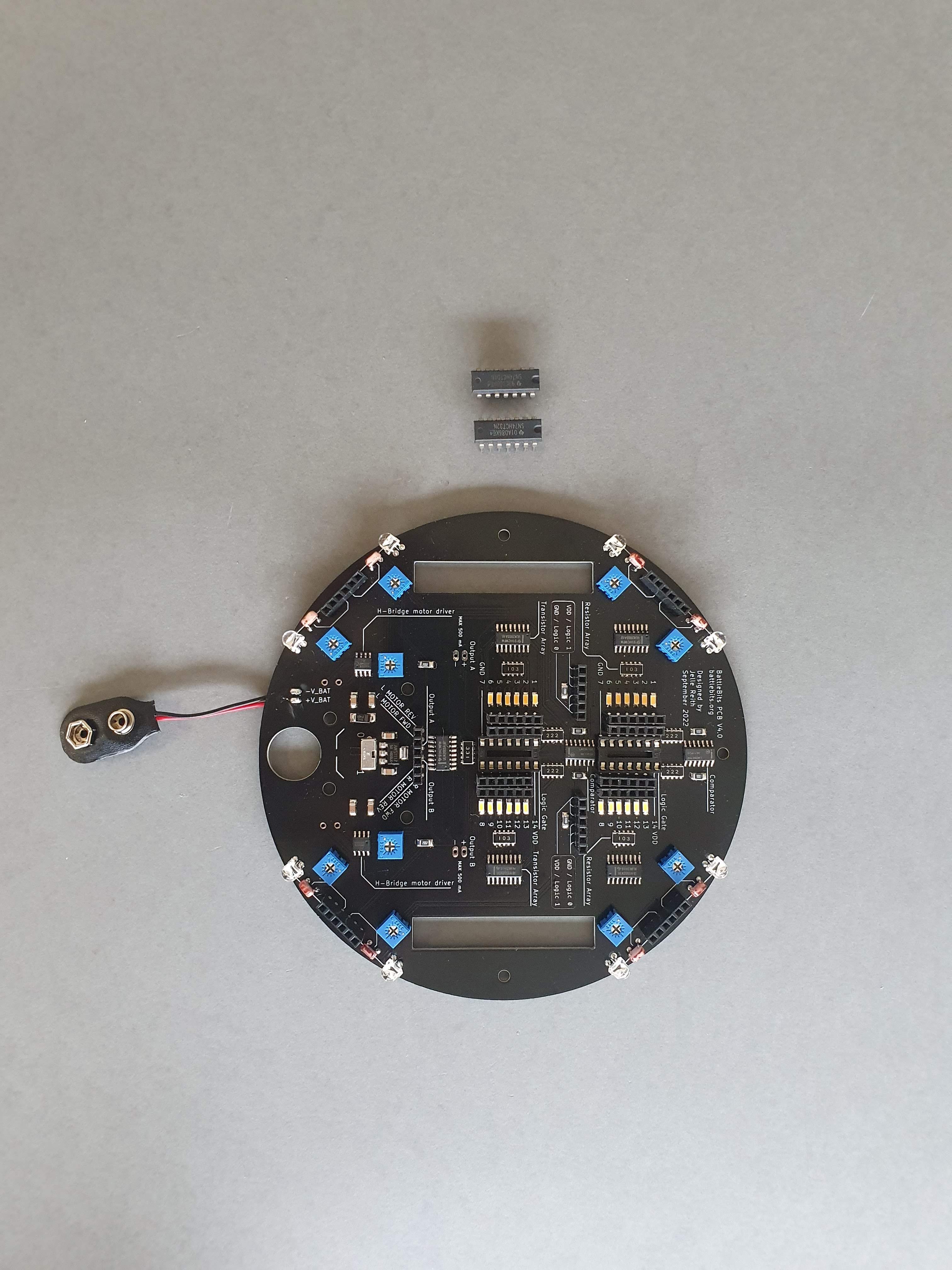
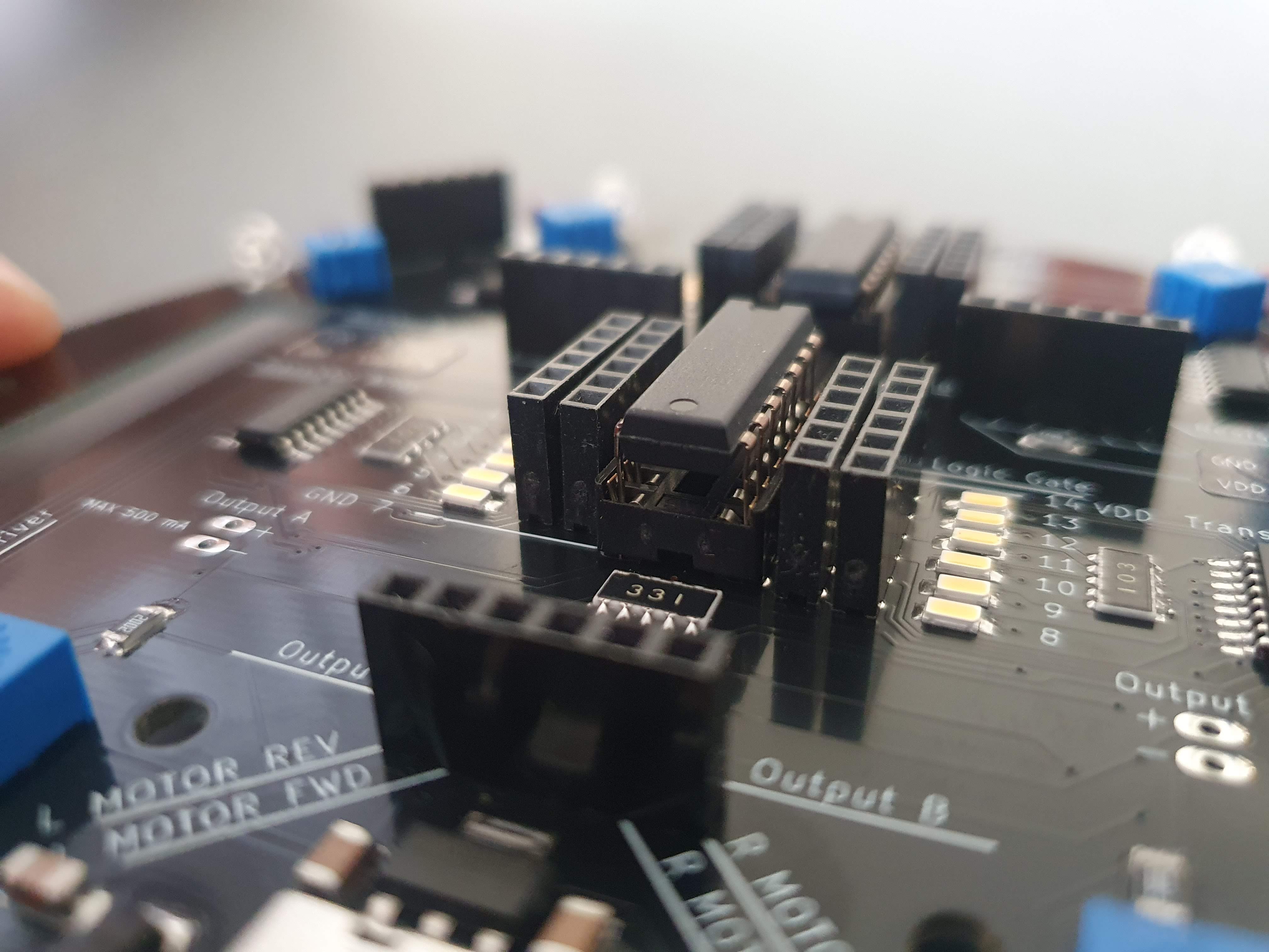
Placing the logic gates
The logic gates are the brains of the BattleBit. In the kit you will find three different logic gates. All the logic gates have their own name e.g. SN74HCT08N. To find out what kind of logic gate you have you can refer to the 7400 series logic gate and truth tables page. On that page you can also find out more about the logic gates and check out the datasheets.
Materials:
- BattleBit PCB
- 2 x Logic gates (AND / OR / NOT)
Steps:
- 1: Use a flat surface to bend the legs of the logic gates in a 90 degree angle
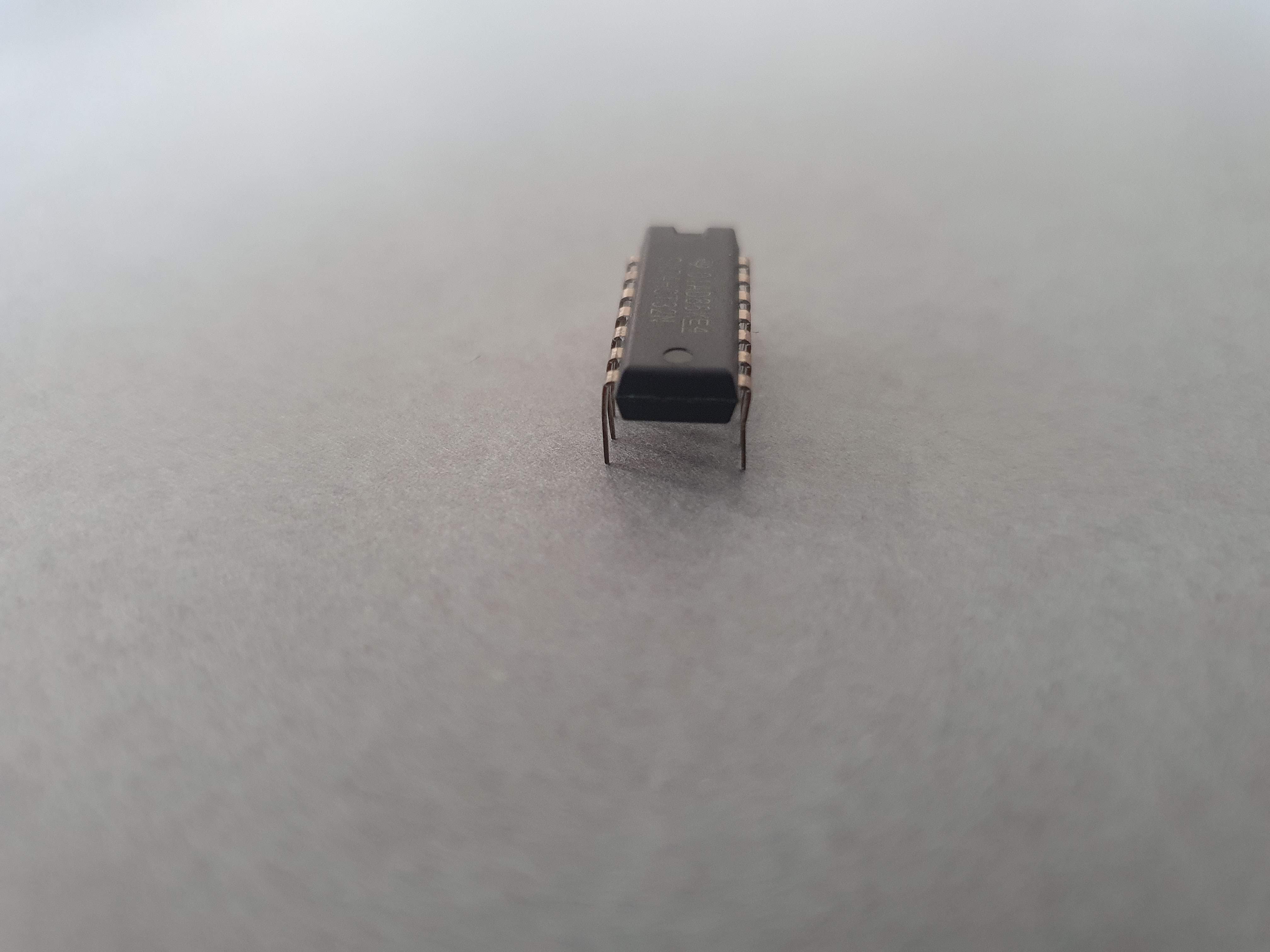
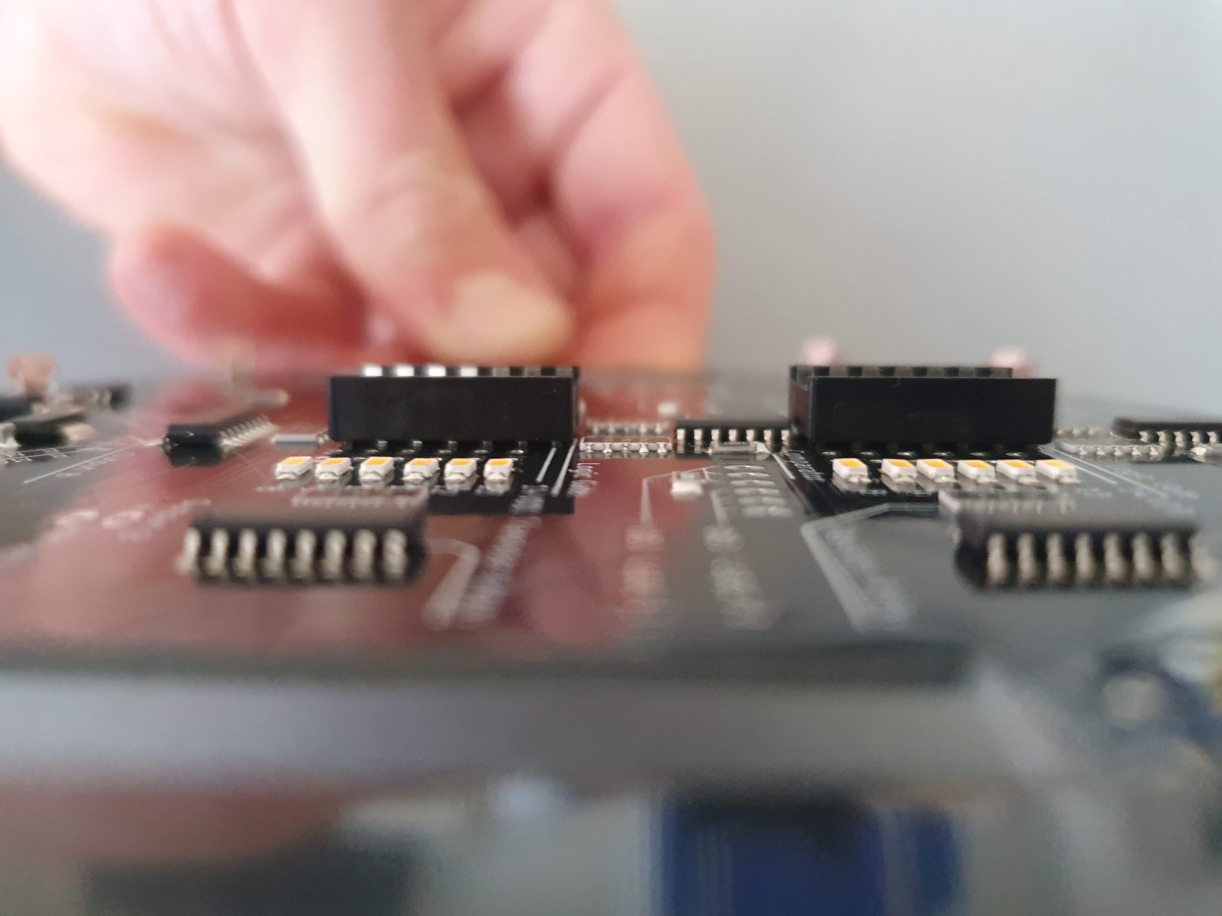
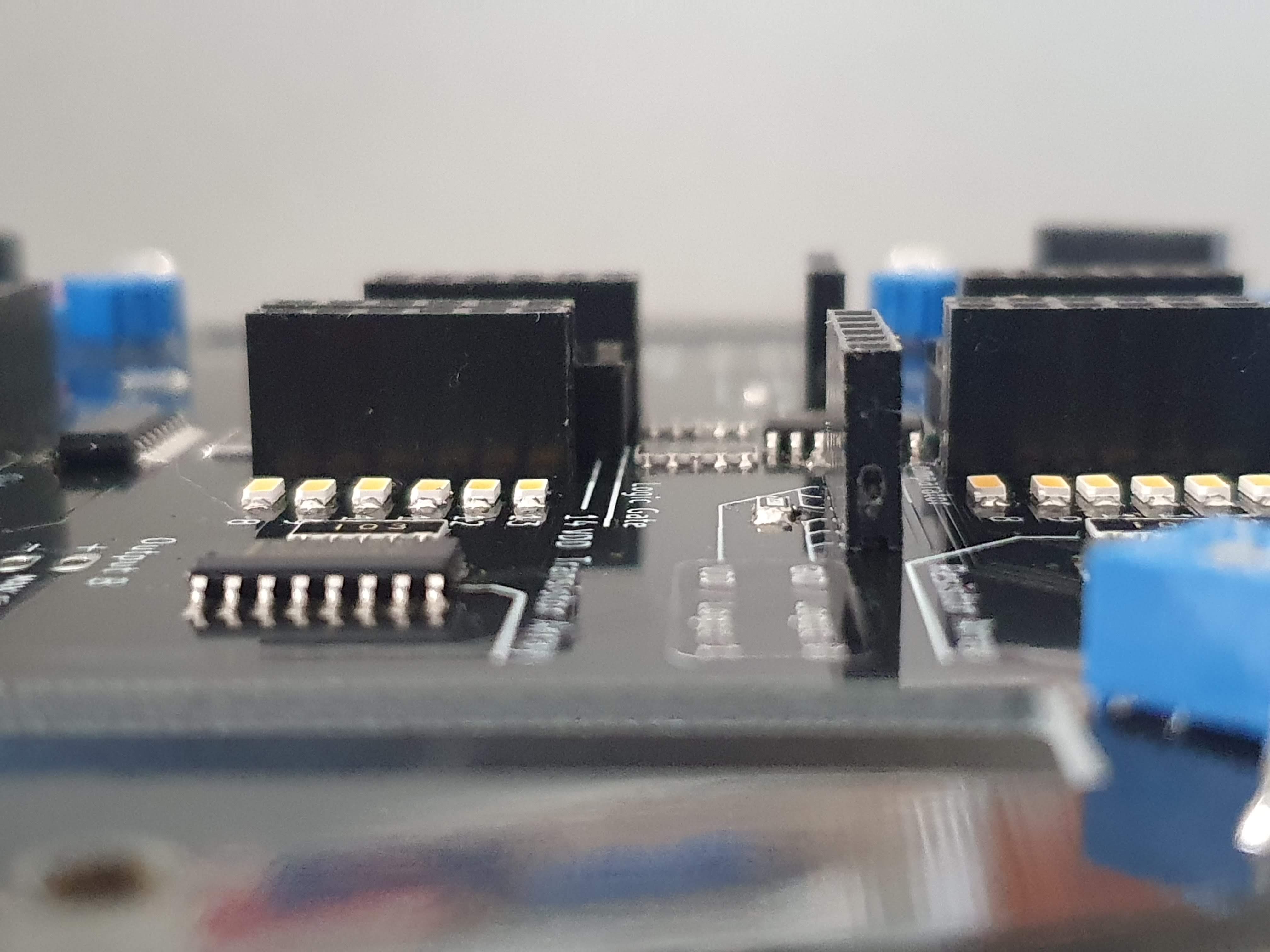
- 2: Carefully push the logic gate into the socket. Make sure the notch of the IC is facing forwards, also make sure all legs are in the correct holes!
First time powering the circuit
Materials:
- BattleBit PCB
- 1 x 9v battery

Steps:
- 1: Make sure that the on/off switch is set to "0"
- 2: Connect the 9v battery
- 3: You can now flick the on/off switch to "1"
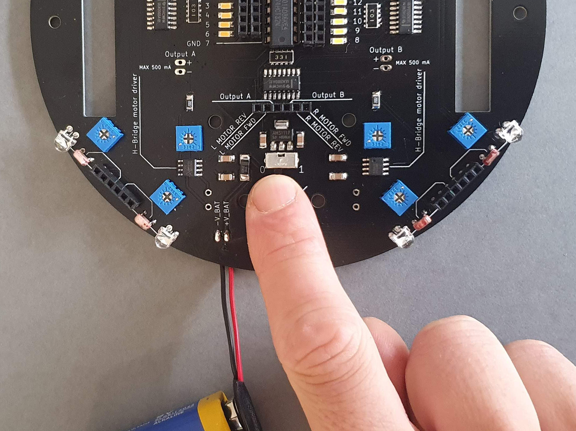
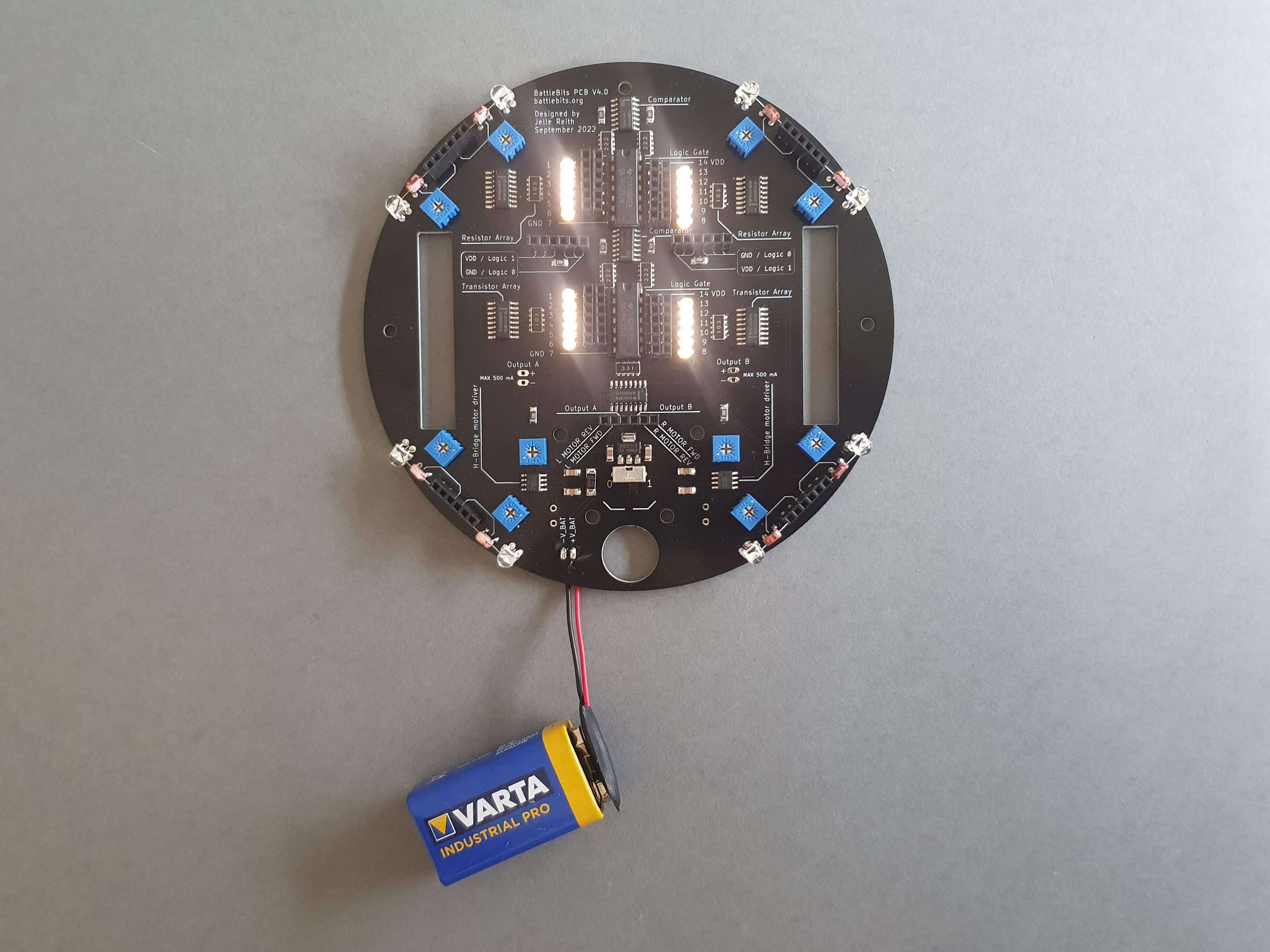
4: If everything is working properly, depending on your logic gates either all or half of the small LEDS should light up: If nothing happens or if the magic blue smoke is escaping from the components something went horribly wrong
5: If the PCB is working properly you can call yourself an expert and maybe help some of your fellow students that have difficulty